 |
|||
|
|
|||
|
Page Title:
BALLISTICS DRIVE INSTALLATION (CONT) |
|
||
| ||||||||||
|
|
 TM 9-1220-220-34
4-5.
BALLISTICS DRIVE INSTALLATION (CONT)
FRAME 2
Step
Procedure
NOTE
Do steps 1 thru 4 only if locator pins were removed from new or different ballistics drive in
frame 1. Go to frame 3 if pins were not removed.
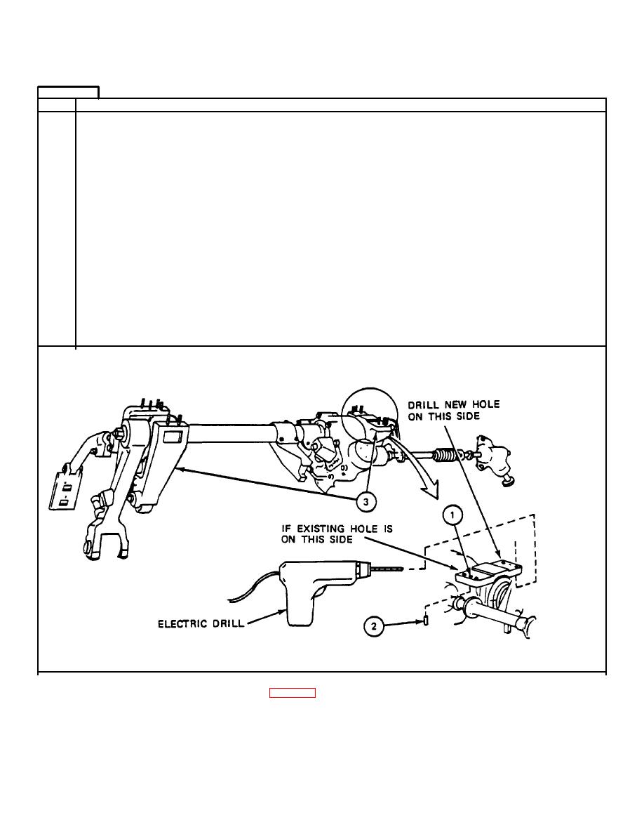
1.
Look to see if right support locator pin hole (1) matches up with the pin hole in turret
mounting pad. If holes do not match up, do steps 2 and 3. If holes do match up, go to
2.
If existing hole is in front of the support bracket, drill new hole in back. Using electric
drill with 15/64" drill bit, drill one hole through right support bracket into turret
mounting pad. Drill hole 1" deep (JPG).
3.
Using reamer, ream hole so that a 1/4" locator pin 1" long can be hammered in.
4.
Using hammer, drive one 1" long, 1/4" diameter locator pin (2) through right support
assembly (3) into turret mounting pad.
GO TO FRAME 3
4-20
|
|
Privacy Statement - Press Release - Copyright Information. - Contact Us |
