 |
|||
|
|
|||
|
Page Title:
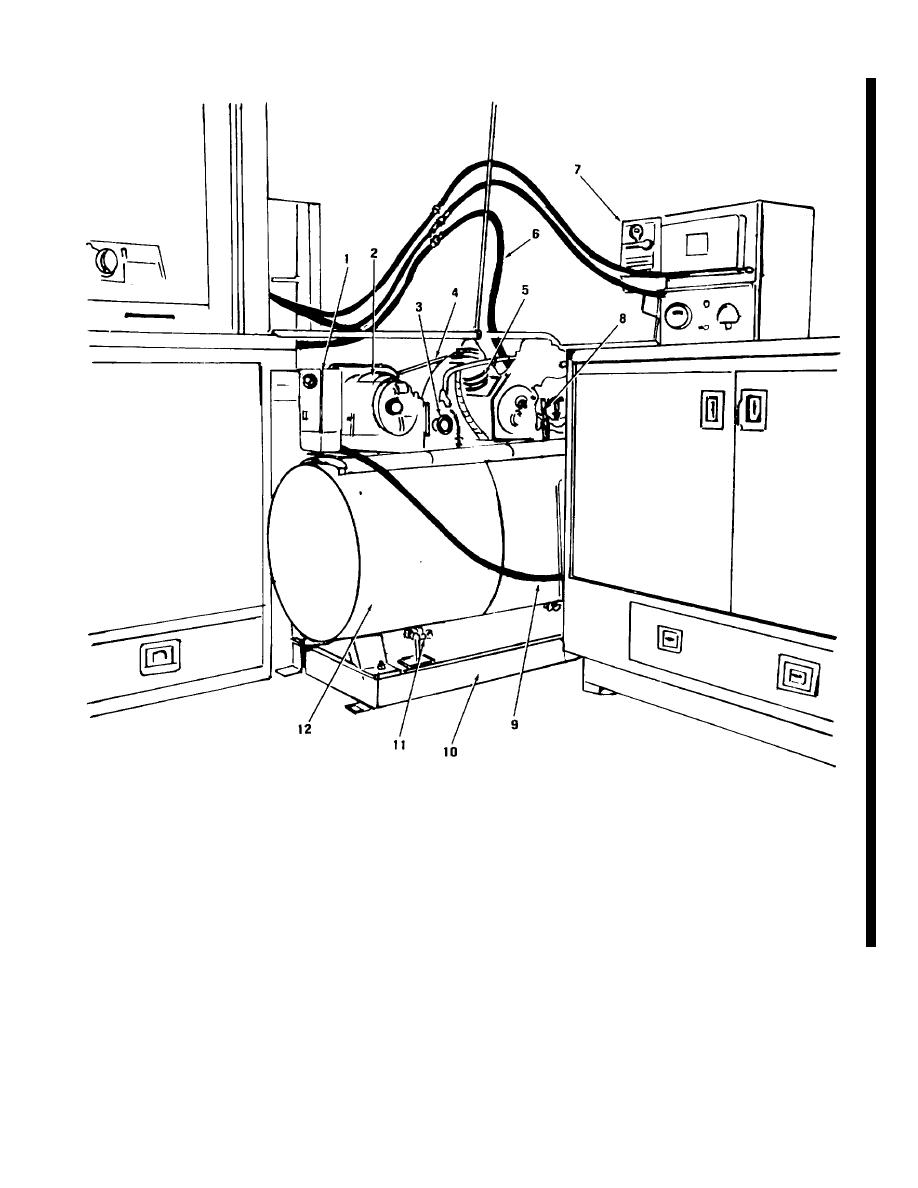
Figure 2-26. Air Compressor (Unit No. 23) |
|
||
| ||||||||||
|
|
 TM 5-6640-214-14
1.
Starting position
7.
Main power switch
2.
Electric motor
8.
Air receiver tank outlet valve and safety valve
3.
Pressure switch and gage
9.
Powerline
4.
Drivebelt
10.
Base
5.
11.
Caster control
6.
Compressed air service line
12.
Air receiver tank
Figure 2-26. Air Compressor (Unit No. 23)
Change 1 2-47
|
|
Privacy Statement - Press Release - Copyright Information. - Contact Us |