 |
|||
|
|
|||
|
Page Title:
CHAPTER 2 OPERATING INSTRUCTIONS |
|
||
| ||||||||||
|
|
 TM 5-6350-264-14&P-4
NAVELEX EE 181-AA-OMI-050/E121 DT546 M9442
TO 31S9-2FSS9-1-4
CHAPTER 2
OPERATING INSTRUCTIONS
Section I. OPERATING PROCEDURES
2-3. EMERGENCY OPERATION.
2-1. CONTROLS AND INDICATORS. There are no
Operation with
incomplete surveillance coverage or faulty tamper
operator controls or indicators applicable to this
circuit should be held to a minimum. Extended periods
equipment.
of operation on battery (stand-by) power should be
2-2. NORMAL OPERATING PROCEDURES. The VS
avoided.
is operational after it has been installed, tested, and
2-4. UNUSUAL OPERATING CONDITIONS.
connected to the J-SIIDS Control Unit. Since the startup
Operation during periods of construction or heavy
and shutdown of the VS are dependent on the presence
vehicular traffic will affect system sensitivity. Faulty
or absence of power from the J-SIIDS Control Unit, no
heating or ventilating equipment operating in the
operating
procedures
are
required.
immediate area will affect system performance.
Section II. THEORY OF OPERATION
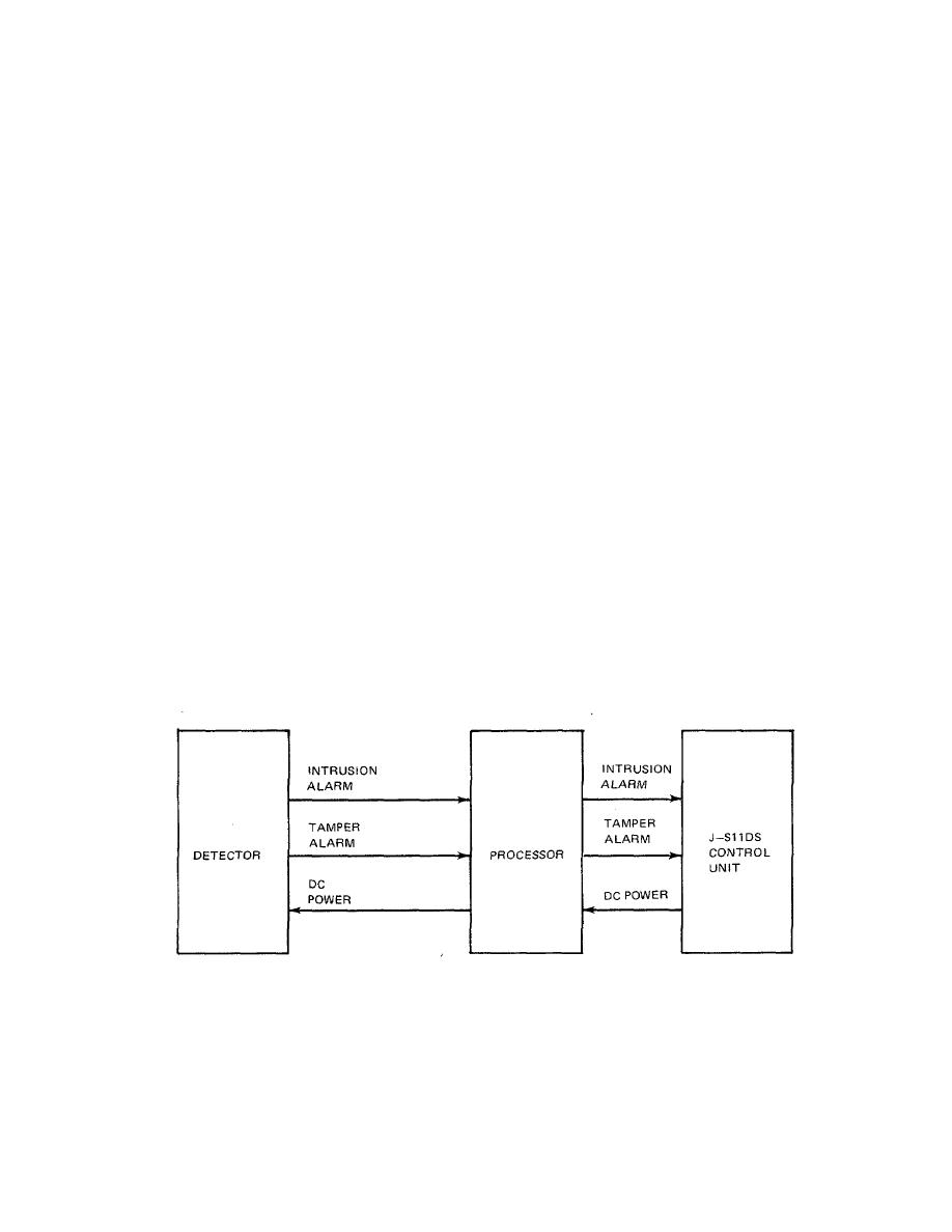
2-5. FUNCTIONAL DESCRIPTION. The VS consists
These vibrations are sent to the Processor which
recognizes a vibration impulse of 100 milliseconds or
of a Processor and up to twenty Detectors for sensing
longer. Four 100-msec pulses within a 15-second
intrusion generated vibrations in the 10- to 15-kHz
period or a single 4.5-second pulse will activate an
(audible) range. Figure 2-1 is a simplified block diagram
alarm in the Processor. The Processor then sends an
of the VS. The VS will detect structurally transmitted
alarm signal to the J-SIIDS Control Unit. A tamper
vibrations resulting from an attempted forced entry by
alarm signal is sent to the Control Unit whenever the
drilling, cutting, burning, or chipping through protective
cover of the Processor or a Detector is opened. The J-
barriers. The Detector will sense vibrations generated
SIIDS Control Unit provides operating power to the VS.
within approximately 3 feet (1 meter) of its position.
Figure 2-1. Vibration Sensor Group Simplified Block Diagram
2-1/(2-2 blank)
|
|
Privacy Statement - Press Release - Copyright Information. - Contact Us |
