 |
|||
|
|
|||
|
Page Title:
Figure 2-2. Method of Preparing Sensor Cable Connections |
|
||
| ||||||||||
|
|
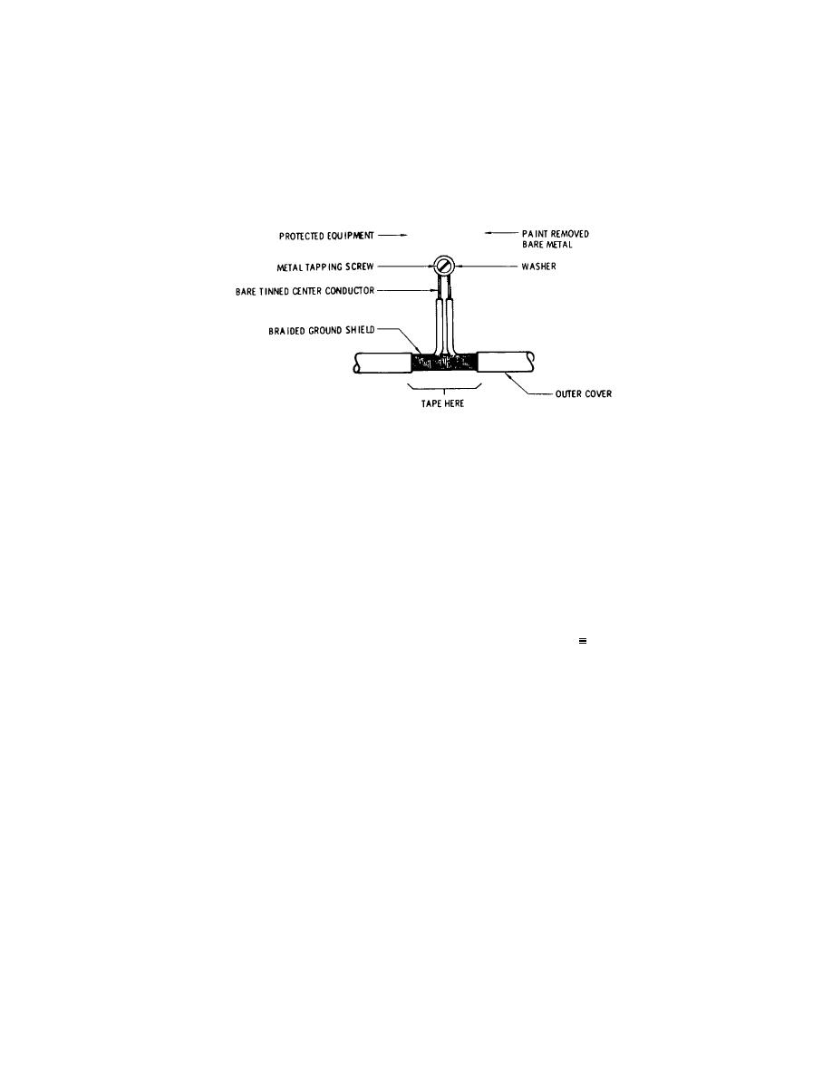 through the opening in the braid, a section of insulation of the center conductor is removed, and the bare center
conductor is fastened to a bare metal spot on the equipment with a metal tapping screw and washer. A wire brush and a
drill motor can be used to clean off paint. The exposed part of the braid must be taped to prevent contact with the
equipment.
e. Fifty feet of RG-58/U coaxial cable is furnished with the equipment. If this is insufficient for the installation,
the cable may be lengthened by splicing additional RG-58/U cable to the end. RG-58/U has a capacitance of
approximately 30.8 picofarads per foot; any cable added must be included in the total maximum permissible protected
capacitance. Furthermore, the 470K ohm terminating resistor must be placed at the far end of the added cable, not at
the end of the original cable.
ME 6350-262-14/13-2-2
Figure 2-2. Method of Preparing Sensor Cable Connections
2-8. Typical Installation Capacities
Typical capacities that can be expected during system operation are as follows:
Item
Capacitive Load
Installation Method
2 drawer file
650 pf
On cement floor
2 drawer file
300 pf
On insulating blocks
Desk
300 pf
On cement floor
Desk
600-700 pf
On tile floor
Safe
300 pf
On cement 1" from
masonry wall
NOTE
All protected items must be metal.
2-9. System Sensitivity
Optimum system sensitivity varies from installation to installation and is a matter of achieving the required detection
capability while keeping probability of false alarm at an acceptable level. This may be achieved by properly setting the
sensitivity switch or, in particularly critical installations, establishing some intermediate level of sensitivity by the use of
series capacitors, as discussed in the following paragraphs.
a. Sensitivity Switch. The sensitivity switch allows a choice of two sensitivities for best performance in the
particular installation. In the HI position, the unit is very sensitive, capable of detecting a person approximately one foot
away from a protected object. The range of protected capacitance in this position is from 0 to 5, 000 picofarads. In the
LO position, the unit is one-third as sensitive to capacitance changes, but its range of protected capacitance is increased
to 15, 000 picofarads. Both required sensitivity and amount of equipment to be protected therefore must be taken into
account, and the sensitivity switch is thus placed in the position where optimum performance is obtained. For example, if
personnel are normally expected to pass by the protected equipment without sounding an alarm, the LO sensitivity
position is recommended so that an alarm will be generated only if persons come very close to or actually touch the
equipment.
b. Initial Switch Position. As a rule of thumb, use the LO sensitivity position initially and check to determine
whether the sensitivity is adequate, since in this position the probability of false alarms caused by moving personnel or
objects in proximity with the
2-3
|
|
Privacy Statement - Press Release - Copyright Information. - Contact Us |
