 |
|||
|
|
|||
|
|
|||
| ||||||||||
|
|
 determined by the degree to which the springs are
5-17. Disconnect
compressed by the bolt and nut which hold the assembly
together.
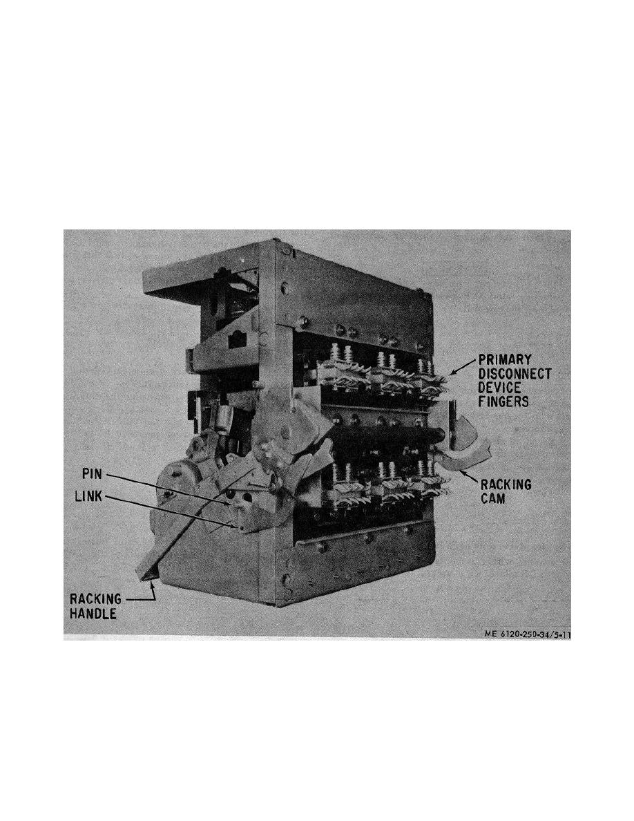
a. General. The disconnects are attached to the
circuit breaker studs at the rear of the breaker. each
b. Disconnects Replacement. If for any reason the
disconnect assembly consists of four pairs of opposed c
disconnects must be replaced or removed, the position of
contact fingers. The contact fingers (fig.5-11) are secured
the nuts on the bolts should be carefully noted and the
to the breaker stud by two bolts which pass through the
number of turns of the nut must be counted This is
assembly and the stud of the enclosure. The disconnect
important because in reassembly the original amount of
fingers exert a set amount of force against the stationary
compression can be restored by replacing the nuts in
stud through the action of the compression springs.
their former position on the bolts.
The primary
Retainers and spacers hold the contact fingers in correct
disconnects should always be kept lubricated with a
alignment for engagement with the stud. The amount of
grease according to the l current Lubrication Order.
force which the fingers exert against the stud is
Figure 5-11. Circuit breaker. right rear oblique view.
and disengage.
5-18. Drawout Mechanism
b. Operation. The drawout mechanism is equipped
a General Drawout breakers are furnished with a
with a drawout trip interlock which prevents a racking
drawout mechanism which facilitates the inserting and
operation from being performed when the breaker is
withdrawing of the breaker from its c compartment It
closed. Inserting the breaker into the compartment
provides a suitable means of forcing the breaker through
causes the racking pins on
the part of inserting and withdrawal operations when the
stationary and movable halves of the disconnect engage
5-15
|
|
Privacy Statement - Press Release - Copyright Information. - Contact Us |