 |
|||
|
|
|||
|
Page Title:
REPLACEMENT of Power sensor Components |
|
||
| ||||||||||
|
|
 5-16
REPLACEMENT of Power sensor Components
NOTE
a. Power Sensor Unit.
No further breakdown of the coil assemblies
(1) Loosen screw ( 1 fig.5-7 ) connecting unit to
should be made. Do not remove coin from
the front frame.
around their iron core.
(2) Slide unit forward.
(6) Install new coil assemblies in reverse order of
(3) Remove control plug alternately loosening the
steps (2) (3) (4), and (5).
two retaining screws.
(7) Connect front and rear frame per paragraph 5-4
(4) Install new unit in reverse order of preceding
d.
steps (1) (2) and (3).
(18) Reinstall circuit breaker per paragraph 2-22.
b. Trip Solenoid.
(1) Remove opening springs (2, fig.5-8).
(2) raise cross bar to gain additional access room
(3) Remove two nuts holding device to bracket.
(4) Remove wiring cleats and connections to terminal
board on Power Supply to free the trip solenoid for
removal.
(5) Install new device in reverse order of steps(1) (2)
(3) and (4).
(6) Check positive trip to obtain ap proximately 1 /32
inch overtravel after armature moved sufficiently to trip
the breaker.
c. Power Supply.
(1) Remove trip solenoid wire. from the terminal
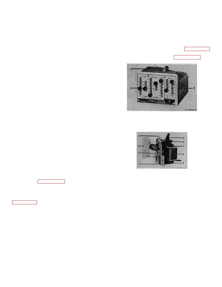
1. Mounting screw
board on power supply.
2. Captive thumb screw
(2) Remove three bolt. holding mounting bracket (6,
3. Name plate
fig.5-9) to mechanism frame.
Figure 5-7. Power sensor unit.
(3) Remove wiring cleats
(4) Remove disconnect plug by alternately loosening
two retaining screws.
(5) Remove power supply unit with control wiring.
(6) Install new device in reverse order of steps (1)
(2), (3) (4), and (5).
d. Sensor Coils.
NOTE
To remove sensor coils the front and rear frames
must he separated. The breaker must be removed
from the drawing mechanism and put on a work
bench.
1.
Name plate
(1) Remove breaker from compartment and drawout
2.
Spring
mechanism per paragraph 2-21.
3.
Mounting bracket
(2) Disconnect plug (4 fig.5-10) between the power
4.
Adjusting screw
supply unit and the sensor coils. Remove tapped screw
5.
Trip arm
holding female plug to breaker mechanism frame.
6.
Armature
(3) Separate front frame from rear frame per
7.
Clamp
8.
Coil
(4) Remove the four bolts connecting each coil
9.
Magnet
assembly to the pole unit.
(5) Remove the Coil assemblies taking care to
Figure 5-8. Magnet trip device
damage
the
interconnecting
coil
wire.
5-13
|
|
Privacy Statement - Press Release - Copyright Information. - Contact Us |
