 |
|||
|
|
|||
|
Page Title:
Figure 2-16. Circuit breaker installation |
|
||
| ||||||||||
|
|
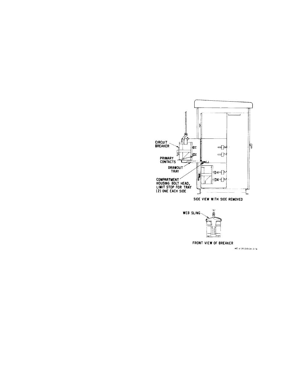 (14)
After completing the fifth racking
(5) Slowly lower the breaker onto the tray
stroke, lift the handle as high as it will go and allow it
guiding it so that the holes in the rear angle of the breaker
to drop to its normal position. This operation will
fit over the two dowel pins on the tray. If the breaker is
reverse the pawl so that it is set for a racking out
correctly positioned on the dowels, its rear and side
operation.
bottom frame angles will all sit firmly on the tray.
(6) Insert two 3/ 8 inch hex head bolts
CAUTION
through the holes in the front of the side angles of the
Any stroke beyond this point will cause the
breaker base. Thread them part way into the tapped
breaker to be trip-free.
holes in the tray. Do not tighten the bolts firmly. ''his will
permit self-alignment of the primary disconnects during
(15) Tighten the 3/8 inch hex head bolts inserted
the subsequent racking operation.
in the front holes of the drawout tray. The breaker is now
(7) Remove lifting device and sling.
aligned and in the "Connected" position.
(8) Push the breaker into the compartment until
the Lest position stop engages preventing further travel.
(9) Release the test position stop by depressing
its lever and push the breaker back into the compartment.
The racking pins on the compartment housing should butt
against the outer surface of the racking cams of the
breaker.
(10) Lift racking handle as high as it will go. This
engages pawl to first notch on the cam.
(11) After pawl engages the first notch on the
cam push handle down to its normal position. This
causes the cam to rotate about the racking pin.
(12) Repeat steps (10) and (5) five times to rack
the breaker into its final "Connected" position. Interlocks
hold the breaker trip-free until it is racked into the fully
"Connected" position.
NOTE
It is imperative that each stroke is performed
with a positive motion and carried to its limiting
position. Once a racking operation has been
started it should be completed. as the breaker
cannot be reversed until the racking operation is
completed.
(13) The fifth stroke of the handle is only a partial
stroke and does not result in any further movement of the
breaker.
NOTE
The fifth stroke serves three useful purposes: I-It
positions the cam so that it cannot rotate and allow
the breaker to back out under short circuit stresses.
2- 'The partial stroke signals that the racking
operation is complete. 3-It releases the trip interlock
Figure 2-16. Circuit breaker installation.
which was engaged by' the racking pin during the
previous four pumps of the racking handle.
2-17
|
|
Privacy Statement - Press Release - Copyright Information. - Contact Us |
