 |
|||
|
|
|||
|
Page Title:
Figure 2-8 Instrument panel, voltmeter and switch |
|
||
| ||||||||||
|
|
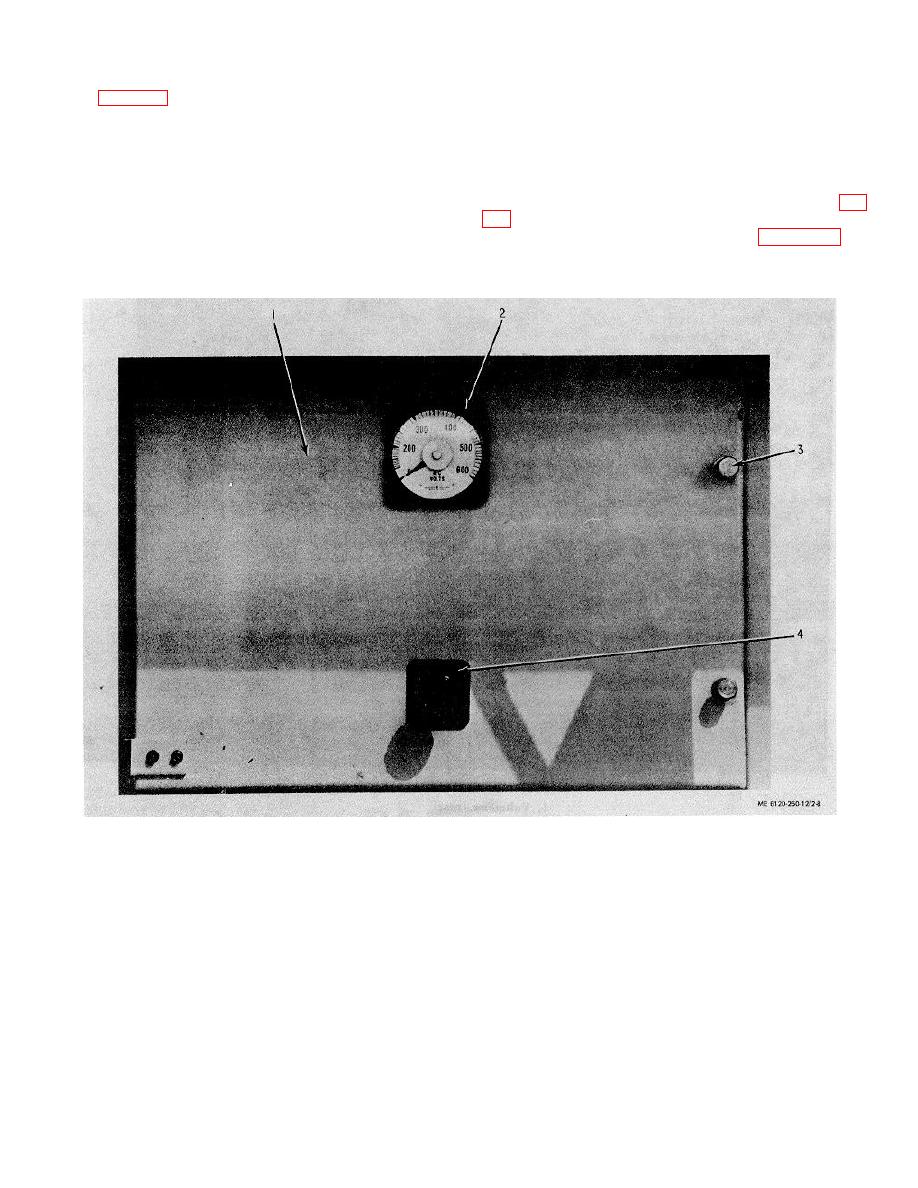 (1) Behind the left front door, the top hinge panel is the
Key to figure 2-7
1
Liquid level gage
instrument compartment. Mounted on the panel is a
type AB-40 voltmeter (2) and a type SB-I voltmeter
2
Winding temperature gage
selector switch (4). The switch has seven positions: off,
3
Pressure - vacuum gage
3 phase to phase (1-2,2-3, 3-1) and 3 phase to neutral
4
Liquid Temperature gage
(1, 2,3). Two knurled captive screws (3) on the right of
5
Reset magnets in holders
this panel secure it. Three potential transformers (3, fig.
6
Name plate
7
Temperature winding auxiliary switch cable
the upper rear of this compartment. See figure 2-10 for
circuit.
c.
Low Voltage Distribution Cabinet (fig. 2-
8).
1.
Panel
2.
3.
Knurled screws
4.
Voltmeter selector switch
Figure 2-8 Instrument panel, voltmeter and switch
2-13
|
|
Privacy Statement - Press Release - Copyright Information. - Contact Us |
