 |
|||
|
|
|||
|
Page Title:
Figure 3-30. Valves and attaching parts. disassembly, reassembly. |
|
||
| ||||||||||
|
|
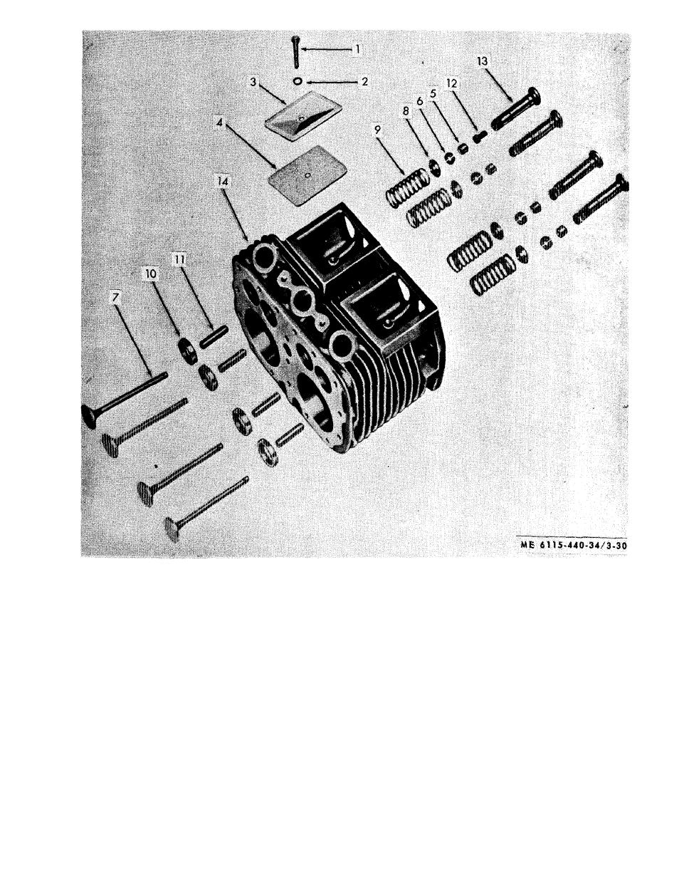 1.
Screw
8. Seat valve spring
2.
Washer
9. Spring
10. Insert, valve seat
3.
Cover Plate
4.
Gasket
11. Valve guide
5.
Rotator Cap
12. Adjusting Screw
6.
Lock
13. Valve lifter
14. Cylinder block
7.
Valve, inlet and exhaust
Figure 3-30. Valves and attaching parts. disassembly, reassembly.
b. Removal.
3-26. Idler Gear
(1) Remove the gear cover (para 3-20).
a. General. The idler gear is located in the gear
(2) Remove idler gear shaft retaining screw
case on a shaft mounted in the engine crankcase. It
and remove gear and shaft as an assembly from the
is driven by the crankshaft gear and in turn drives
engine crankcase (fig. 3-31).
the magneto gear and the oil pump gear. The idler
c . D i s a s s e m b l y . Refer to figure 3-31B and
gear shaft is secured in the crankcase by a retaining
disassemble the idler gear and shaft.
screw (A, fig. 3-31).
3-36
|
|
Privacy Statement - Press Release - Copyright Information. - Contact Us |
