 |
|||
|
|
|||
|
Page Title:
Figure 3-25. Piston and Connecting rod, disassembly and reassembly. |
|
||
| ||||||||||
|
|
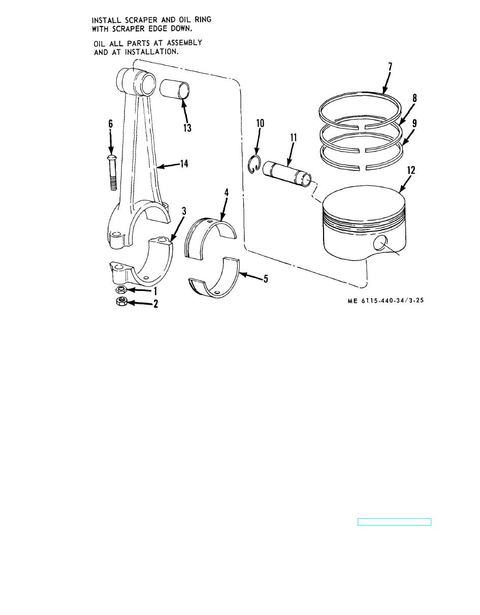 8.
Scraper ring
1.
Locknut
9.
Oil ring
2.
Nut
10.
Retaining ring
3.
Connecting rod caps
11.
Piston pin
4.
Lower half bearing
12.
Piston
5.
Upper half bearing
13.
Bushing
6.
Bolt
14.
Connecting rod
7.
Compression ring
Figure 3-25. Piston and Connecting rod, disassembly and reassembly.
d. Inspection.
3-24. Engine Cylinder Blocks
(1) Inspect the cylinder blocks for cracks,
a. General. The engine cylinder blocks are one
broken fins, and other damage. Check cylinder
piece castings with removable hardened valve seat
bore for out-of-round.
inserts and guides. The cylinder block assemblies
(2) Replace cylinder block if damaged or if
are interchangeable and will fit either the right or
cylinder bore is worn 0.005 inch or more.
left bank of the crankcase.
e. Reassembly. Refer to figure 3-27 and
b. Removal.
reassemble engine cylinder block.
(1) Remove the manifold (TM 5-6115-440-
f. Installation.
20).
(1) Refer to figure 3-26 and install the engine
(2) Remove the cylinder head (fig. 3-23).
cylinder block.
(3) Remove the piston and connecting rods
(2) Install the piston and connecting rod (para
(para 3-23).
3-23).
(4) Refer to figure 3-26 and remove the engine
(3) Install the cylinder head (fig. 3-23).
cylinder block.
(4) Install the manifold (TM 5-6115-440-20).
c. Disassembly. Refer to figure 3-27 and
disassemble the engine cylinder block.
3-31
|
|
Privacy Statement - Press Release - Copyright Information. - Contact Us |
