 |
|||
|
|
|||
|
|
|||
| ||||||||||
|
|
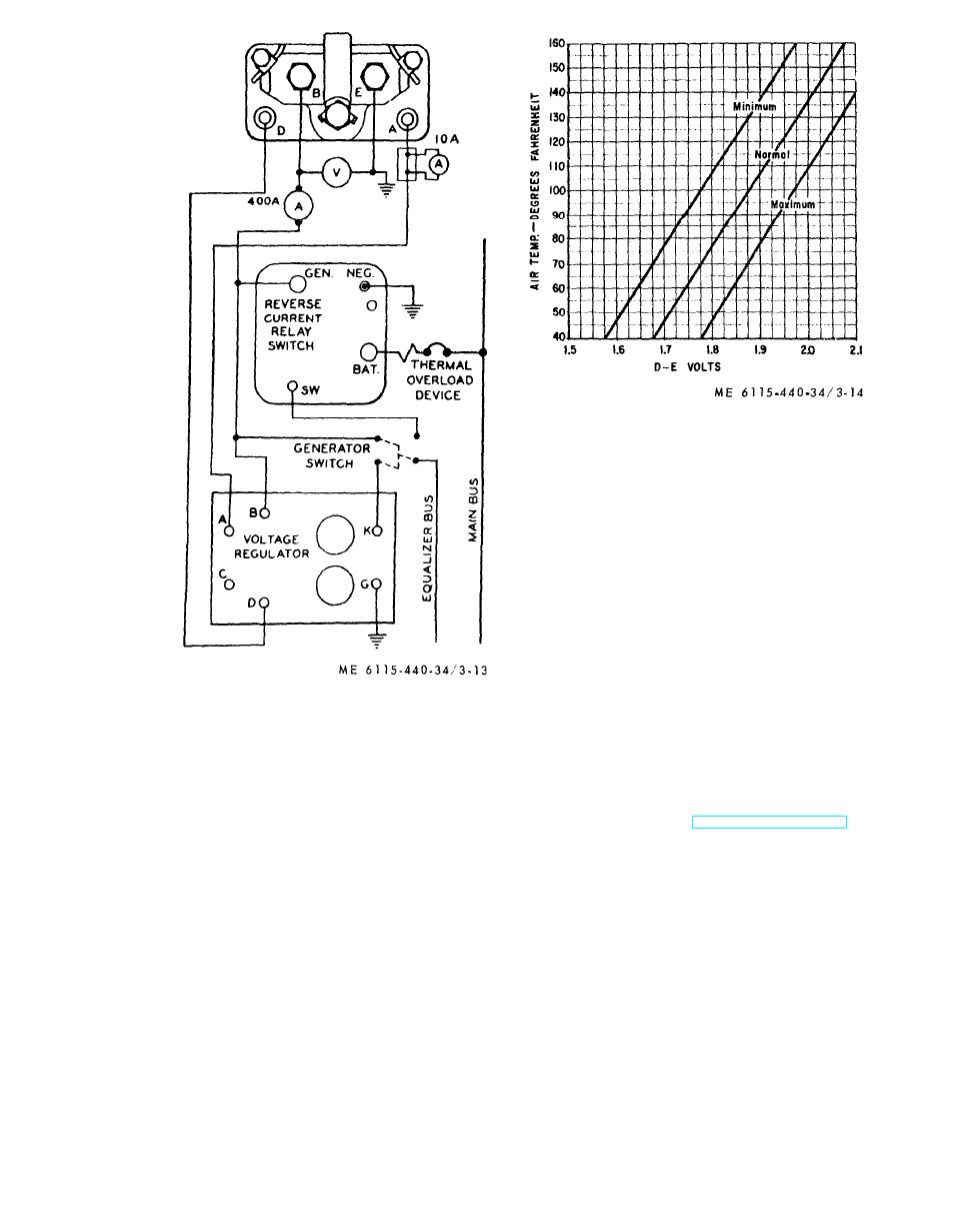
 Figure 3-14. Calibration chart for
paralleling voltage.
Figure 3-13. Electrical test connection,
starter-generator assembly.
Section IV. ENGINE ASSEMBLY
3-17. General
magneto are covered in TM 5-6115-440-20 and
This section contains repair and replacement in-
above sections. See figure 3-15 for a location view
s t r u c t i o n for the basic engine components. Ac-
of the basic engine components.
cessory items such as the carburetor, fuel pump and
3-19
|
|
Privacy Statement - Press Release - Copyright Information. - Contact Us |