 |
|||
|
|
|||
|
Page Title:
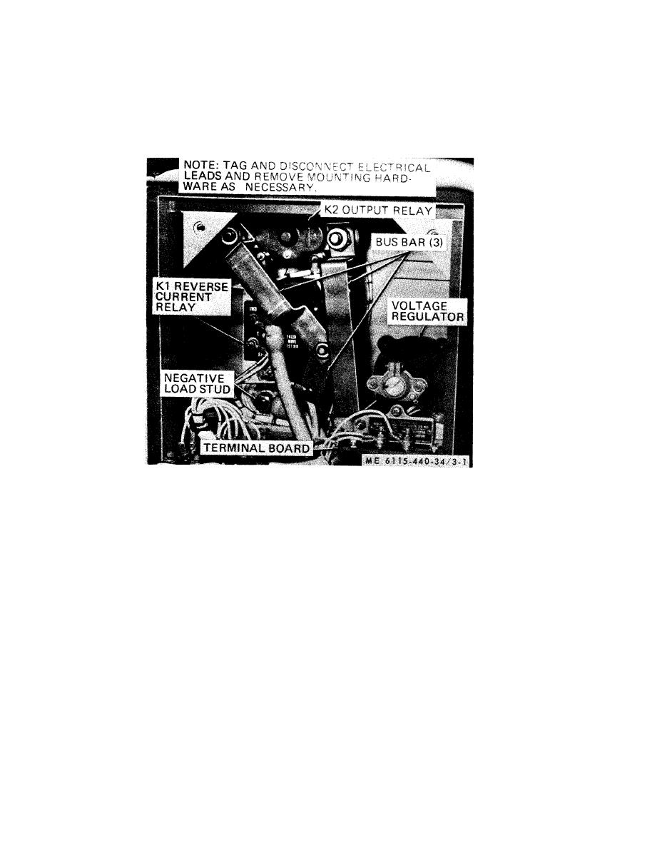
Figure 3-1. Control box components, removal and installation. |
|
||
| ||||||||||
|
|
 2.75 volts when the switch is closed. If the voltage
the rheostat to 28.0 volts at 4375 rpm, no-load,
drop does not fall between the above limits, replace
after this check.
the coil. If there is no change, check for an open
(14) Safety wire the clamping screw on the
shock mount, if used.
equalizer circuit. If a rise occurs, check for reversed
equalizer connections.
(15) Hipot all terminal studs together to the
resistor housing at 600 volts, 60 cycles for one
(13) Lower the speed to 4375 rpm at no-load.
Move the rheostat through it travel to determine if
second.
it will adjust the voltage from 26 to 30 volts. If this
h. Installation. Refer to figure 3-1 and install the
is not the case, recheck the coil current. g(6). Set
voltage regulator.
Figure 3-1. Control box components, removal and installation.
3-3
|
|
Privacy Statement - Press Release - Copyright Information. - Contact Us |
