 |
|||
|
|
|||
|
|
|||
| ||||||||||
|
|
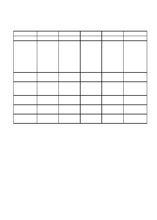
 2E + Bays
13
14
15
16
17
L/Nose
6N1
7N1
7N1
7N1
8N1
1p7
1p7
1p7
1p7
Boom
1p7
TP7 thru
TP7 thru
TP7 thru
TP7 thru
Remove
TP7 thru
Bp4
Bp5
BP4
BP4
BP4
8N1**
7N1*
7N1*
6N1*
7N1*
BP4
7N1*
(1p3)
(1p3)
(1p3)
(1p3)
(1p0)
(CG)
Boom
2p0
2p0
2p0
2p0
2p0
Remove
PIN at A
PIN at A
PIN at A
PIN at A
PIN at A
Boom
1p4
1p4
1p4
1p4
1p4
Remove
TP4 thru
TP4 thru
TP4 thru
TP4 thru
TP4 thru
BP2
BP2
BP2
BP2
BP2
Boom
Bp0
Bp0
Bp0
Bp0
Bp0
Remove
TP2, 1
TP2, 1
TP2, 1
TP2, 1
TP2, 1
Boom
Bp2
Bp2
Bp2
Bp2
Bp2
Remove
E
E
E
E
E
Complete
Note d
Note d
Note d
Note d
Note d
by:
NOTES:
a.
Remove all curbs, ramps, and deck units.
b.
Position CRB under bridge min. 1.5 ft (0.5 m) from end.
c.
Add LNCG posts, LNCG and nose roller and install launching
nose, observing minimum 5 ft (1.5 m) overhang.
d.
Disassemble FRB and RRB. Clear site.
Remove 8th LNH (after BP5)or all of 3N2 (after BP6).
**
*
Remove given length of launching nose, LNCG, LNCG posts and
nose roller.
()
Center of gravity.
2-43
|
|
Privacy Statement - Press Release - Copyright Information. - Contact Us |