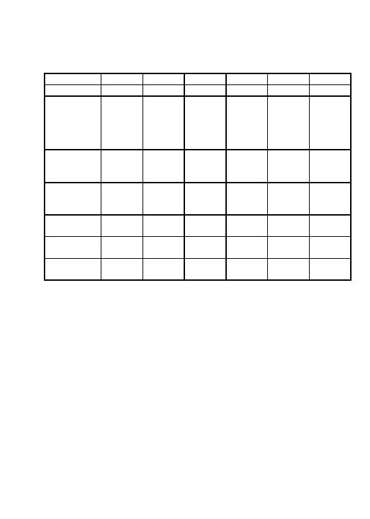
 |
|||
|
|
|||
|
|
|||
| ||||||||||
|
|
 2E + Bays
7
8
9
10
11
12
L/Nose
4N1
5N1
5N1
5N1
6N1
6N1
Boom
1p7
1p7
1p7
1p7
1p7
1p7
Remove
TP5
TP6, 5
TP6, 5
TP6,5
TP6, 5
TP6, 5
BP4
BP4
BP4
BP4
BP4
BP4
4N1*
5N1*
5N1*
5N1*
6N1*
6N1*
(CG)
(1p3)
(1p3)
(1p3)
(1p3)
(1p3)
(1p3)
Boom
2p0
2p0
2p0
2p0
2p0
2p0
Remove
Pin
Pin
Pin
Pin
Pin
Pin
at A
at A
at A
at A
at A
at A
Boom
1p4
1p4
1p4
1p4
1p4
1p4
Remove
TP4
TP4
TP4
TP4
TP4
TP4
3, BP2
3, BP2
3, BP2
3, BP2
3, BP2
3, BP2
Boom
Bp0
Bp0
Bp0
Bp0
Bp0
Bp0
Remove
1
TP2, 1
TP2, 1
TP2, 1
TP2, 1
TP2, 1
Boom
Bp2
Bp2
Bp2
Bp2
Bp2
Bp2
Remove
E
E
E
E
E
E
Complete
Note e
Note e
Note e
Note e
Note e
Note e
by:
NOTES:
a.
Remove curbs, decks and ramps and position FRB under
bridge min. 1.5 ft (0.5m) from end.
b.
Position center of LR (in LRP) 8 ft (2.4 m) from BSB.
c.
Add LNCG posts, LNCG and nose roller. Add 3LNH.
Re-position LRP [base 9 in (23 cm) from BSB].
d.
For 2E + 1 only. Add 2 LNH and LLN.
e.
Add remaining nose sections, as required observing the
minimum 5 ft (1.5 m) overhang.
f.
Disassemble FRB and RRB. Clear site.
*
Remove entire launching nose, LNCG, LNCG posts and nose
roller.
()
Center of gravity.
2-41
|
|
Privacy Statement - Press Release - Copyright Information. - Contact Us |