 |
|||
|
|
|||
|
Page Title:
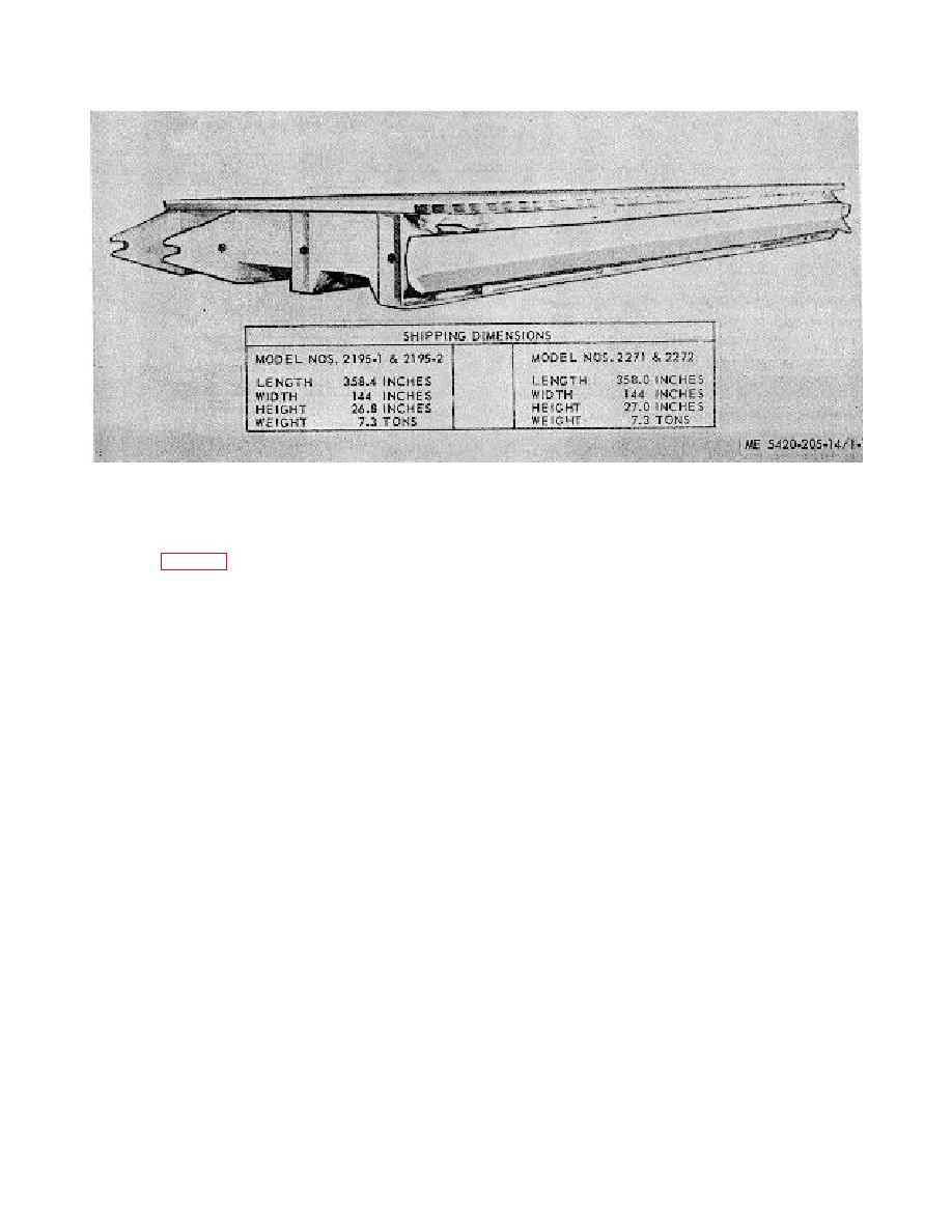
Figure 1-1. Interior bay superstructure, three-quarter view with shipping dimensions. |
|
||
| ||||||||||
|
|
 TM 5-5420-205-14
Figure 1-1. Interior bay superstructure, three-quarter view with shipping dimensions.
and left approach ramps can easily be arranged and
b. End Bay Superstructure. The end bay
vehicle headings kept in the same direction. The
superstructure (fig. 1-2) is comprised of two basic
hinged portion of the ramp superstructure can be
elements: (1) a deck section similar to the interior
rotated only after it has been connected to another
bay superstructure but approximately 14 feet, 9
vehicle. After that connection has been made, it is
inches long; and (2) a tapered ramp approximately
rotated upward and outward to the desired
22 feet, 9 inches long which can be rotated by
position. The ramp can be adjusted in grade
hydraulic cylinders controlled from the vehicle cab
positions ranging from any angle upslope to 15
to form the approach ramp for bridges and ferries.
percent down slope. In the desired position the
The sections are fabricated of aluminum alloy and
ramp unfolding cylinders are hydraulically locked
steel. The hinges joining the 2 ramp sections are of
to secure the hinged joint from turning when the
high strength steel. The end and interior bay
load moves onto the bridge. The maintenance
superstructures are adaptable to and transported
paragraphs of this manual contain detailed
by the same type transporter. The direction of
descriptions of the interior bay superstructure
rotation of the ramp for assembly into bridge or
components.
ferry position is controlled by a simple pin at-
tachment between the main girders, so that right
1-2
|
|
Privacy Statement - Press Release - Copyright Information. - Contact Us |