 |
|||
|
|
|||
|
Page Title:
Table 7-3. Troubleshooting Intercommunication Switchboard SB-2601/G - Continued |
|
||
| ||||||||||
|
|
 TM 32-5895-227-14&P
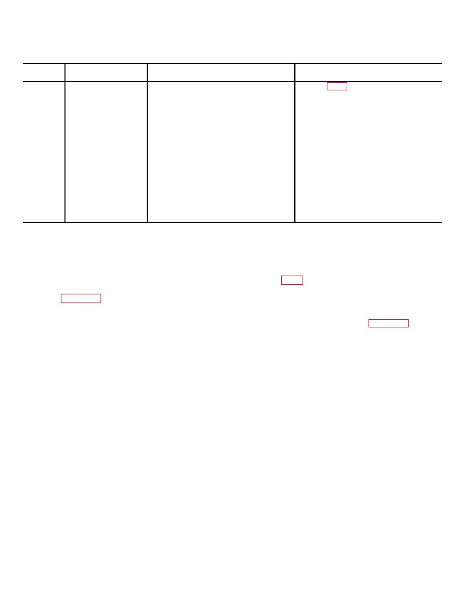
Table 7-3. Troubleshooting Intercommunication Switchboard SB-2601/G - Continued
Item
Trouble symptom
Probable trouble
Corrective action
number
Defective corresponding relay KO
Refer to FO-6. Transfer function of any
5
Inability to transfer
through K9
one station; check for presence of 20
any one of the
Vdc at relay coils KO through K9. If 20
following groups of
Vdc is present and relay is not
stations on a specific
energized, relay is defective. Remove
channel:
and replace relay.
STATIONS: 1- 9
10-19
20-29
30-39
40-49
50-59
60-69
70-79
80-89
90-99
indicated. The rear view of the RICS shows the proper
7-9 TROUBLESHOOTING SB-2602/G.
jack location for intercommunication channels I through
a. General. Perform the procedures indicated
10 and transfer control and special stations 1 through 6
below for sectionalizing, localizing, and isolating trouble
connections.
to a particular circuit in the Radio Intercept Control
(2) The wiring diagram for the RICS is
Switchboard (RICS) SB-2602/G.
shown in FO-7. This diagram indicates a complete
b. Diagrams.
electrical means of performing maintenance on this unit.
(1) The location diagram for the RICS is
It consists of power supplies, blinker circuit, audio
shown in figure 7-5. There are ten transfer channels
volume compression unit, connectors, switches, relays,
and six special stations which indicate the corresponding
and associated wiring.
switches and relays. Location of power supplies No. 1
and No. 2 components, blinker board, and AMP 1
trouble symptoms, the probable troubles, and the
through AMP 4 boards are
corrective actions to be taken.
7-10
|
|
Privacy Statement - Press Release - Copyright Information. - Contact Us |