 |
|||
|
|
|||
|
Page Title:
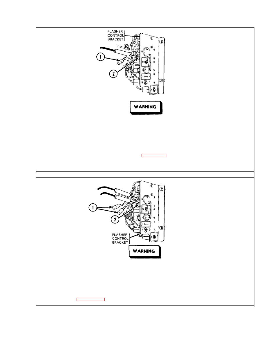
Filter Bypass Indicator Circuit. (Cont) |
|
||
| ||||||||||
|
|
 TM
9-2350-238-20-2
(1)
Filter bypass indicator is off when level wind circuits are not operating.
Make
sure
MASTER
switch
is
OFF
before
repairing
electrical
com-
ponents. Failure to observe this warning could result in injury to
personnel.
Step 1.
Disconnect lead 326 (1) from circuit breaker (2) output. Place red probe in
circuit breaker receptacle. Ground black probe. Set MASTER switch ON. If
multimeter indicates about 24 volts, repair lead 326 between circuit breaker
and line disconnect, refer to page
2-66. If multimeter indicates
no
voltage,
go to step 2. Set MASTER switch
OFF. Connect lead.
Make
sure
MASTER
switch
is
OFF
before
repairing
electrical
com-
ponents. Failure to observe this warning could result in injury to
personnel.
Step 2.
Disconnect both leads 326 (1) from circuit breaker (2). Connect multimeter
to receptacles of circuit breaker. If multimeter indicates continuity, repair
lead 326 between circuit breaker finity, replace circuit breaker, refer to
page 2-297. Set MASTER switch OFF. Connect leads.
|
|
Privacy Statement - Press Release - Copyright Information. - Contact Us |
