 |
|||
|
|
|||
|
Page Title:
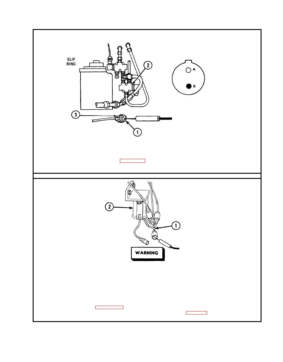
BOOM AND WINCH INSTALLATION (Cont) |
|
||
| ||||||||||
|
|
 TM
9-2350-238-20-2
Step
5. P l a c e r e d p r o b e o n s o c k e t B ( 1 ) ( G N D ) . G r o u n d b l a c k p r o b e . I f m u l t i m e t e r
indicates continuity, notify direct support maintenance for replacement of
solenoid directional control valve (2). If multimeter indicates
infinity,
repair
GND lead, refer to page 2-66. Connect connector (3).
Make
sure
MASTER
switch
is
OFF
before
repairing
electrical
com-
ponents. Failure to observe this warning could result in injury to
personnel.
Disconnect
lead
480
(1)
from
inoperative
traversing
circuit
at
rectifier
(2).
Step 6.
Place
red
probe
in
lead
480.
Ground
black
probe.
Set
MASTER
switch
ON.
Set LEVEL WIND switch ON. Press sensing switch of inoperative traversing
circuit to close. If multimeter indicates about 24 volts, replace rectifier,
refer to page 2-271. If multimeter indicates no voltage, repair lead 480 be-
tween rectifier and sensing switch, refer to page 2-66. Set MASTER switch
OFF. Set LEVEL WIND switch OFF. Connect lead.
2-29
|
|
Privacy Statement - Press Release - Copyright Information. - Contact Us |
