 |
|||
|
|
|||
|
|
|||
| ||||||||||
|
|
 TM 9-2350-238-20-1
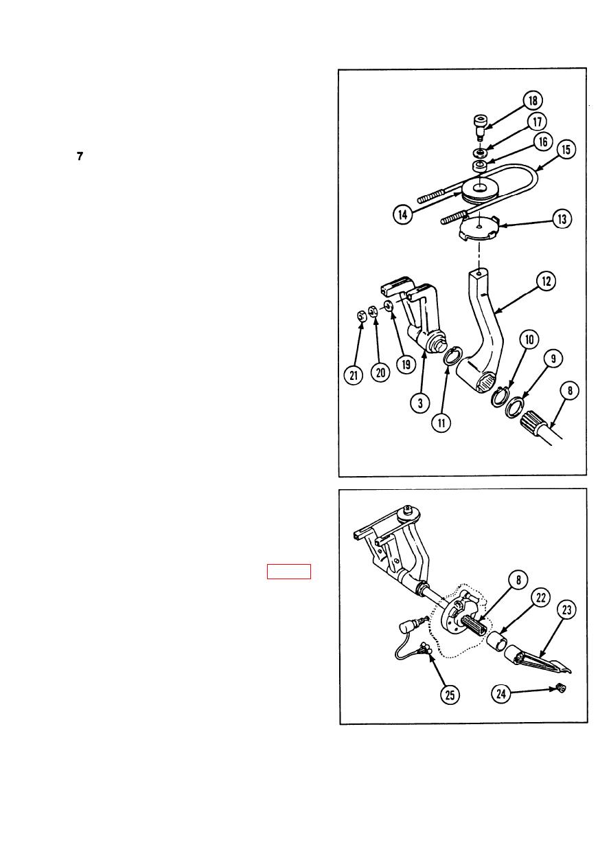
Partially install straight shaft (8) into
5
driver's compartment.
6
Install ring spacer (9) and retaining ring
(10) on straight shaft (8).
Install retaining ring (11) inside manual
control lever (12).
8
Lubricate blind spline of straight shaft (8).
Refer to TM 9-2350-238-10. Align with
blind spline in manual control lever (12),
and install manual control lever.
From driver's compartment side, push
9
against straight shaft (8) so that manual
control lever (12) is forced flush against
remote control lever (3). Ensure that ring
spacer (9) and retaining ring (10) are
seated on straight shaft (8).
Install brake clip assembly (13), groove
10
pulley (14), brake control cable (15), and
sleeve bearing (16).
Install flat washer (17) and shoulder screw
11
(18) .
Install two flat washers (19), two hexagon
12
plain nuts (20), and two new self-locking
nuts (21) on brake control cable (15).
Install tube coupling (22) and brake pedal
13
(23) on straight shaft (8).
Apply sealing compound (item 37, appx C)
14
to threads of pipe plug (24). Install and
torque pipe plug at 20 to 23 ft-lb (27 to 31
N-m).
15
Connect three electrical connectors (25) of
brake warning sensitive switch.
Set parking brake.
16
2-823
|
|
Privacy Statement - Press Release - Copyright Information. - Contact Us |
