 |
|||
|
|
|||
|
|
|||
| ||||||||||
|
|
 TM 9-2350-238-20-1
10 Install electrical lead 515 through pin hole D in electrical insert (7) and rubber bushing (6).
11 Install electrical lead 514 through pin hole E in electrical insert (7) and rubber bushing (6).
12 Install electrical lead 20 through pin hole F in electrical insert (7) and rubber bushing (6).
202, method 303.
14 Install insulation tape (11) on electrical wires (9) where insulation was stripped back. Make 0.5
in. (1.27 cm) overlapping turns to ensure that leads are adequately covered.
NOTE
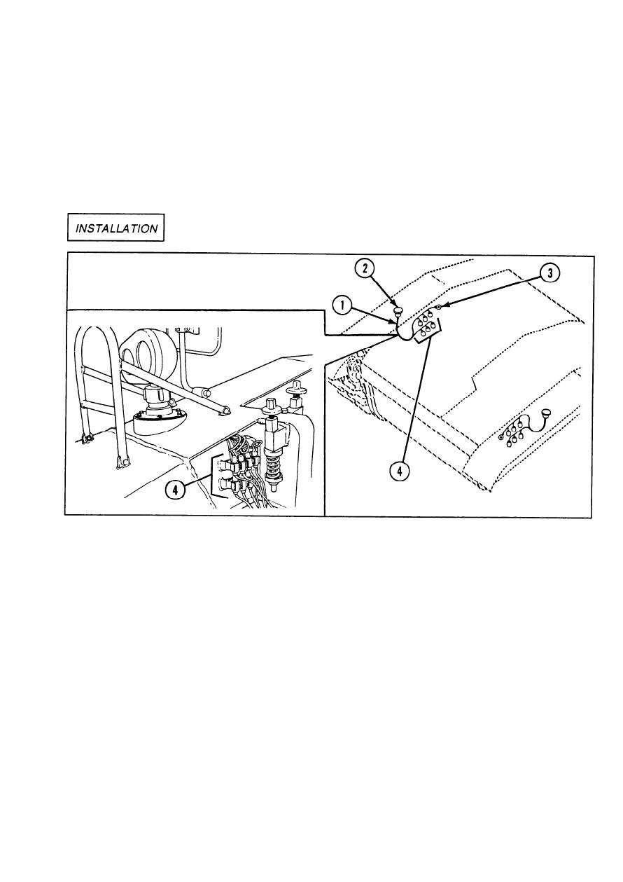
Procedures to install disconnect to headlamp wiring harness are written for the right
side, but apply to both the right and left sides.
Install right disconnect to headlamp wiring harness (1) to hull.
1
Slide headless connectors base assembly (2) into hull.
2
3
Connect cable terminal (3) to ground on right disconnect to headlamp wiring harness (1).
Untag and connect six shell connectors (4) to line connections on right disconnect to headlamp
4
wiring harness (1).
Wiring harnesses and leads are secured to the hull and components with loop clamps, straps,
5
clips, ground screws, etc. During installation, make sure the wiring harness or lead is secure
and all hardware is tight.
2-723
|
|
Privacy Statement - Press Release - Copyright Information. - Contact Us |
