 |
|||
|
|
|||
|
|
|||
| ||||||||||
|
|
 TM 9-2350-238-20-1
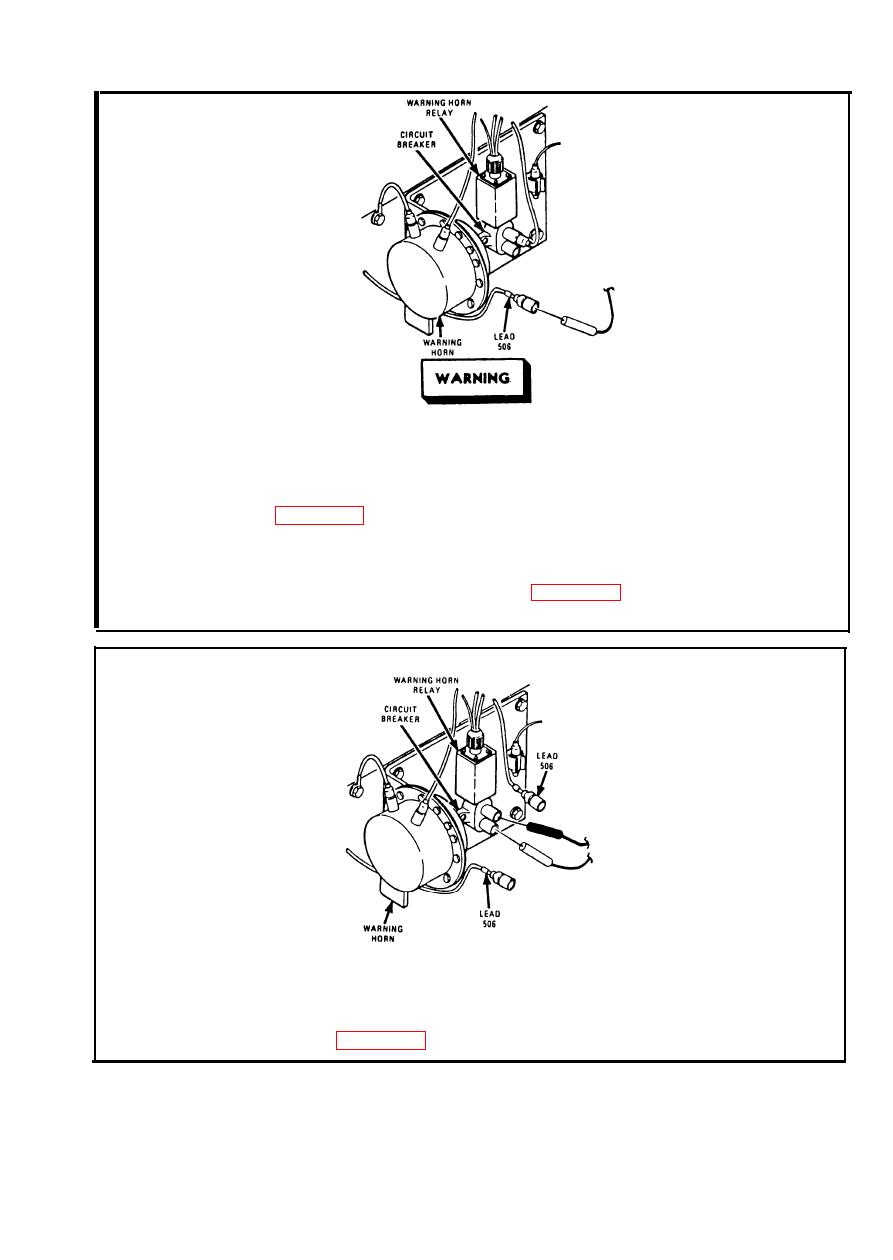
Make sure MASTER switch is OFF before repairing
electrical circuits. Failure to observe this warning
could result in injury to personnel.
Step 1.
To access warning horn and circuit breaker, remove driver's seat. Refer to
probe in lead 506. Ground black probe. Set MASTER switch ON. Set
INST switch ON. If multimeter indicates about 24 volts, go to step 2. If
multimeter indicates no voltage, repair lead 506 between GEN WARNING
light and circuit breaker. Refer to page 2-371. Set MASTER switch OFF.
Set INST switch OFF.
Step 2.
Disconnect lead 506 from circuit breaker output. Place red probe in input
side of circuit breaker. Place black probe in output side of circuit breaker.
If multimeter indicates 0 ohms, connect leads 506 to circuit breaker and go
to step 3. If multimeter does not indicate 0 ohms, replace circuit breaker.
Refer to page 2-637.
2-185
|
|
Privacy Statement - Press Release - Copyright Information. - Contact Us |
