 |
|||
|
|
|||
|
Page Title:
FUEL LEVEL INDICATOR CIRCUIT. (Cont) |
|
||
| ||||||||||
|
|
 TM 9-2350-238-20-1
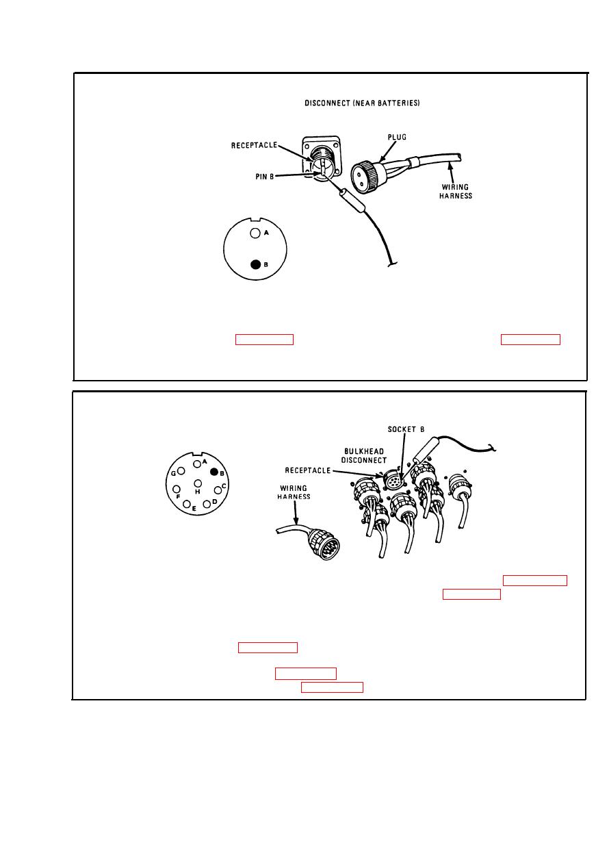
Step 7.
Disconnect wiring harness to instrument (gage) panel. Place red probe on
pin B (lead 28) of receptacle. Ground black probe. If multimeter indicates
about 30 ohms, repair lead 28 between plug and FUEL LEVEL indicator,
refer to page 2-371; and install fuel level transmitter, refer to page 2-626.
If multimeter does not indicate about 30 ohms, go to step 9. Connect
wiring harness to instrument (gage) panel.
Step 8.
To access bulkhead disconnect, remove driver's seat, refer to page 2-952;
and remove driver's compartment aft cowl, refer to page 2-928. Discon-
nect wiring harness at bulkhead disconnect. Place red probe in socket B
(lead 28) of receptacle. Ground black probe. If multimeter indicates about
30 ohms, repair lead 28 between disconnect and bulkhead disconnect.
Refer to page 2-371. If multimeter does not indicate about 30 ohms, repair
lead 28 between bulkhead disconnect and disconnect near magnetic
clutch. Refer to page 2-371. Connect wiring harness. Install fuel level
transmitter. Refer to page 2-626.
2-169
|
|
Privacy Statement - Press Release - Copyright Information. - Contact Us |
