 |
|||
|
|
|||
|
|
|||
| ||||||||||
|
|
 TM 9-2350-238-20-1
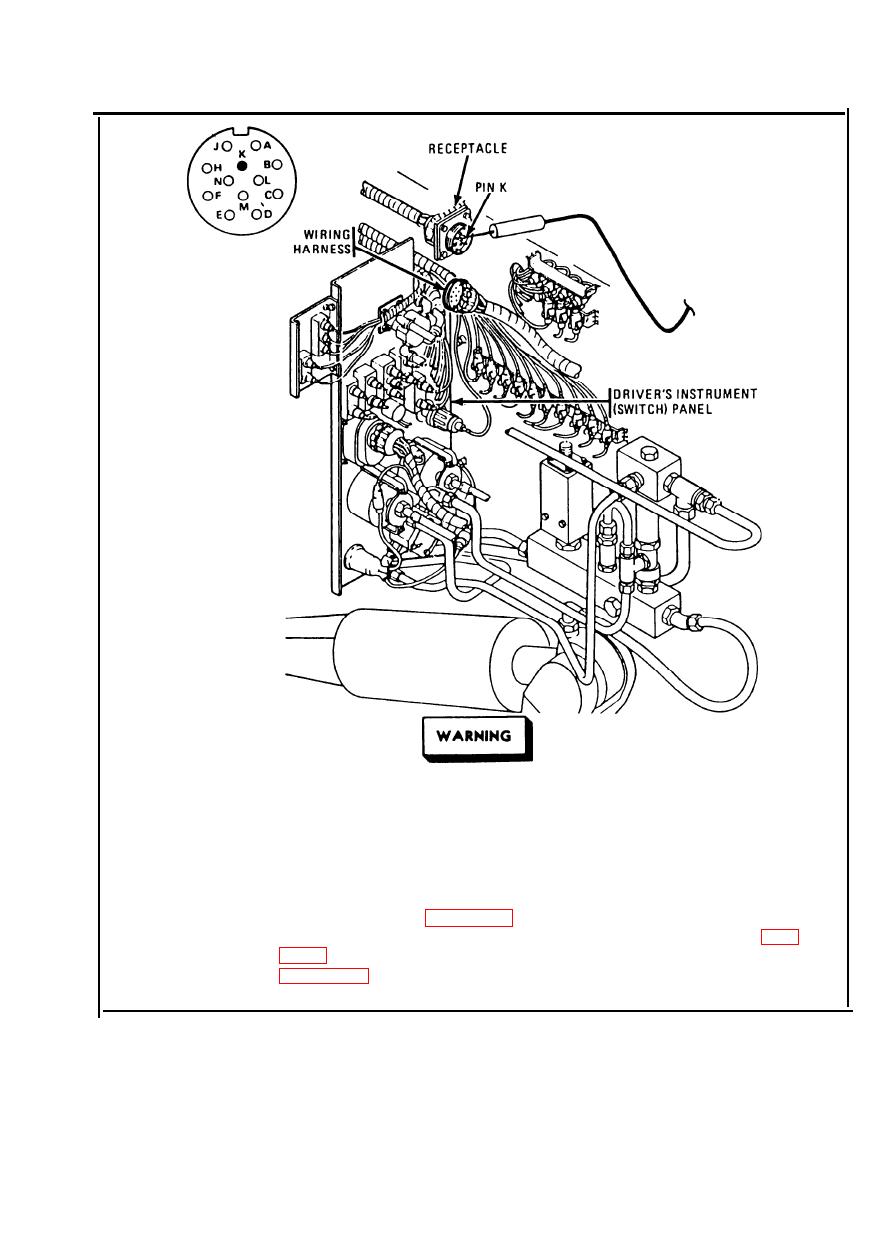
Make sure MASTER switch is OFF before repairing
electrical circuits. Failure to observe this warning
could result in injury to personnel.
Disconnect wiring harness. Place red probe on pin K (lead 459) of
Step 7.
receptacle and ground black probe. Set MASTER switch ON. If
multimeter indicates no voltage, repair lead 459 from MASTER switch to
receptacle. Refer to page 2-371. If multimeter indicates about 24 volts
and problem still exists, troubleshoot master relay circuit, refer to page
receptacle.
2-101
|
|
Privacy Statement - Press Release - Copyright Information. - Contact Us |
