 |
|||
|
|
|||
|
Page Title:
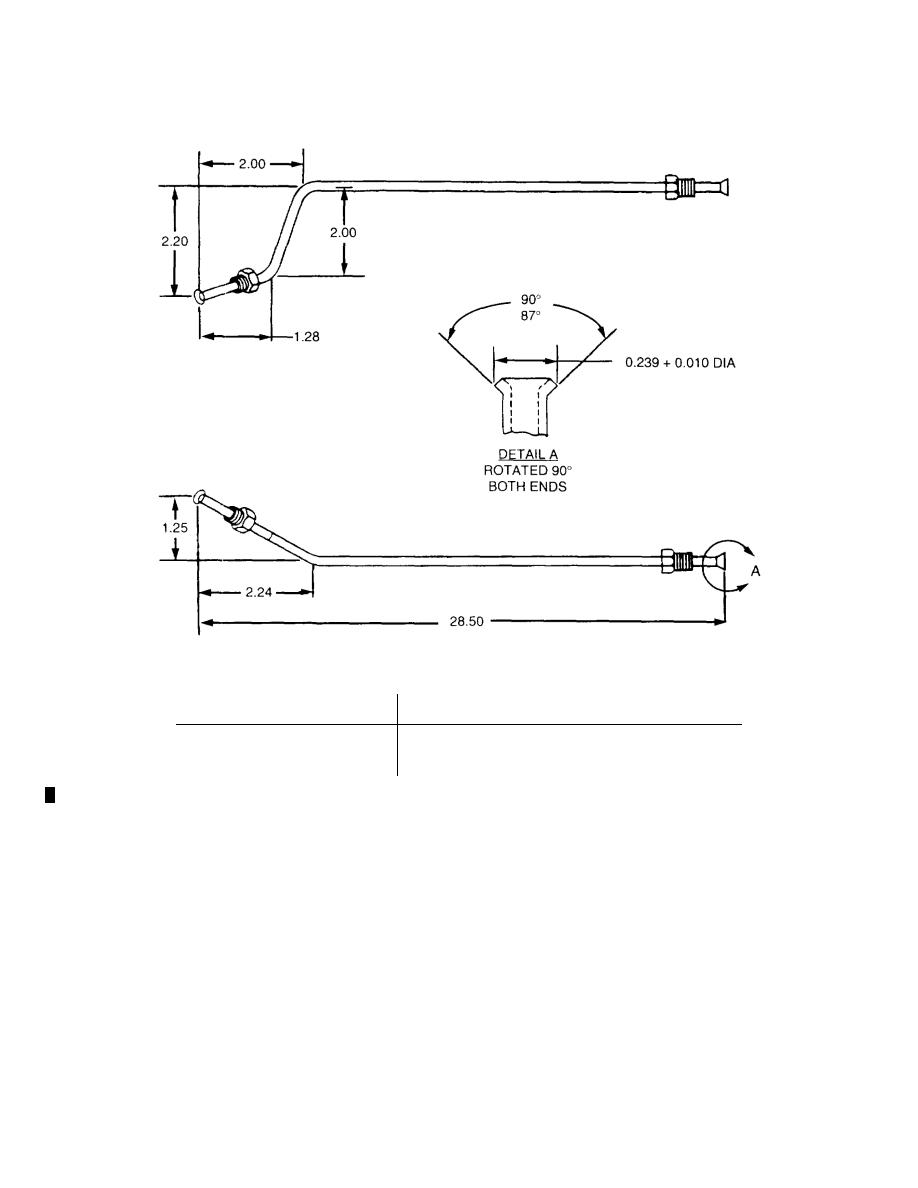
Figure G-5. Hydraulic Brake Tube Assembly, Left and Right (M101A2, M116A2, and M116A2E1) |
|
||
| ||||||||||
|
|
 TM 9-2330-202-14&P
438-115
PART NUMBER
POSITION
11686103-1
Left Side (As Shown)
11686103-2
Right Side (Opposite of Shown)
1.
Fabricate from tube, part number M3520-B80B01G, NSN 4710-00-350-9896.
2.
Cut to proper length and bend as shown.
3.
Install nut, part number 110357, on each end of tube assembly, as shown.
|
|
Privacy Statement - Press Release - Copyright Information. - Contact Us |
