 |
|||
|
|
|||
|
|
|||
| ||||||||||
|
|
 TM 9-2330-202-14&P
DRAWBAR REPLACEMENT.
This Task Covers:
a.
Removal
b. Installation
Initial Setup:
Tools/Test Equipment:
Intervehicular cable removed from road-side
drawbar (para 4-30).
General mechanic's tool kit (Item 1, Appendix B)
Chassis wiring harness removed from road-
Common No. 1 tool set (Item 2, Appendix B)
side drawbar, if removing road-side drawbar
Materials/Parts:
Self-locking nut, MS21044-N8
Hydraulic brake lines removed from curb-side
Self-locking nut, MS51922-49
drawbar, if removing curb-side drawbar (para
Equipment Conditions:
Hydraulic brake actuator assembly removed (as
applicable) (para 4-38).
Fixed front support leg removed (as applicable)
NOTE
The procedure for removing and installing drawbars is the same for left side and
right side.
a.
REMOVAL
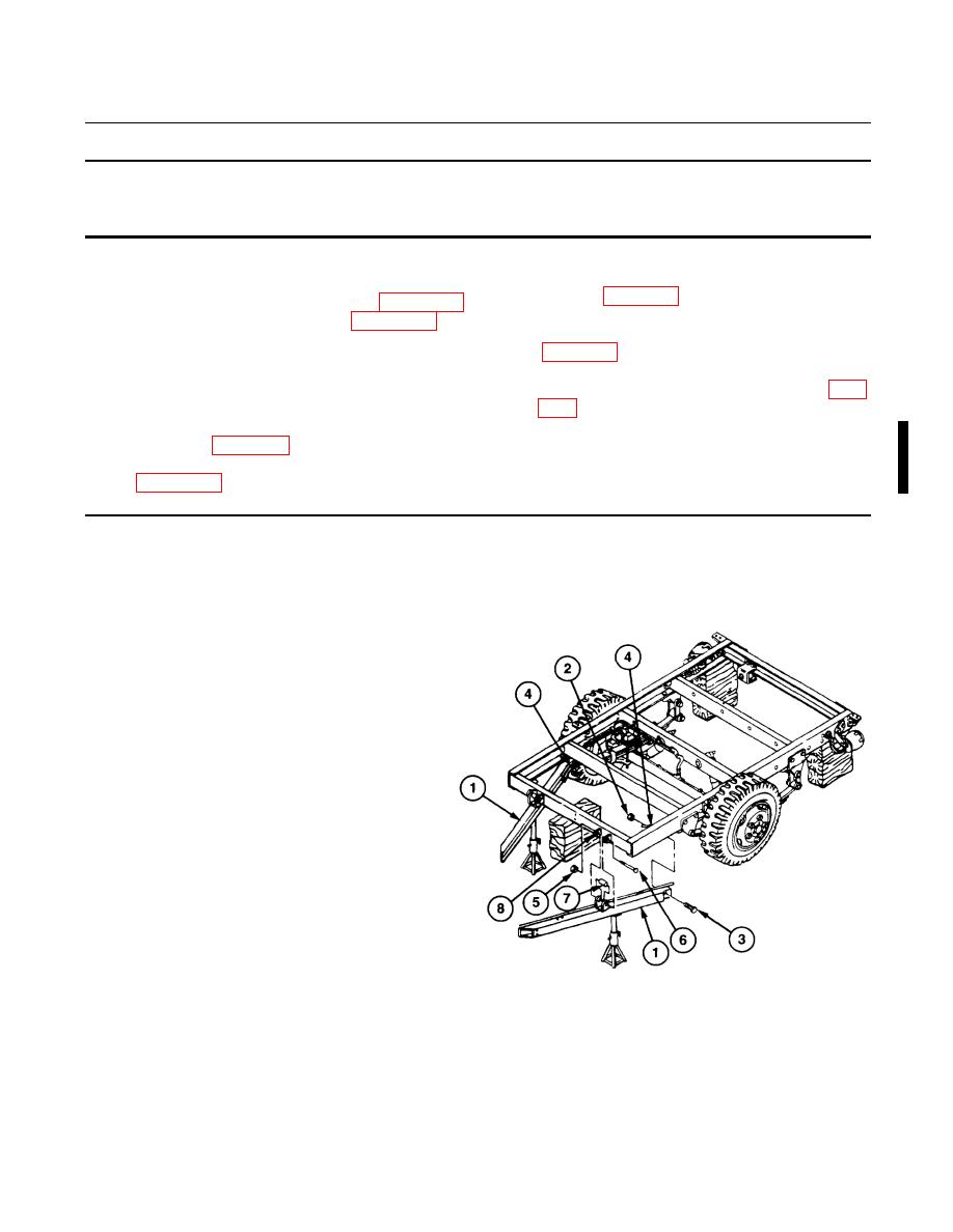
1.
Raise trailer and place suitable sup-
port at rear corners and at midpoint of
vehicle.
2.
Place jackstand under drawbar (1)
being removed.
3.
Remove self-locking nut (2) and cap-
screw (3) from drawbar (1) and front
spring hanger (4). Discard self-locking
nut.
4.
Remove self-locking nut (5), capscrew
(6), and spacer (7) from drawbar (1)
and two eyebolts (8). Discard self-
locking nut.
438-104
|
|
Privacy Statement - Press Release - Copyright Information. - Contact Us |
