 |
|||
|
|
|||
|
Page Title:
HYDRAULIC BRAKE LINES REPLACEMENT |
|
||
| ||||||||||
|
|
 TM 9-2330-202-14&P
HYDRAULIC BRAKE LINES REPLACEMENT.
This Task Covers:
a.
Front Tube Assembly Removal
b.
Front Tube Assembly Installation
c.
Rear Tube Assembly Removal
d.
Rear Tube Assembly Installation
e.
Hose Assembly Removal
f.
Hose Assembly Installation
g.
Left and Right Tube Assemblies Removal
h.
Left and Right Tube Assemblies Installation
Initial Setup:
Tools/Test Equipment:
Lockwasher, MS35338-44
General mechanic's tool kit (Item 1, Appendix B) Self-locking nut, MS51922-6 (M101A2, M101A3,
Common No. 1 tool set (Item 2, Appendix B)
M116A2, and M116A3)
Materials/Parts:
Rag (Item 13, Appendix F)
NOTE
Use a suitable container to catch any draining brake fluid. Make sure all spills are cleaned up.
Quantity of mounting hardware varies slightly with model. Quantities indicated in task are for the
M101A3 and the M116A3.
For information on manufacturing tube assemblies, refer to Appendix G.
a.
FRONT TUBE ASSEMBLY REMOVAL
1.
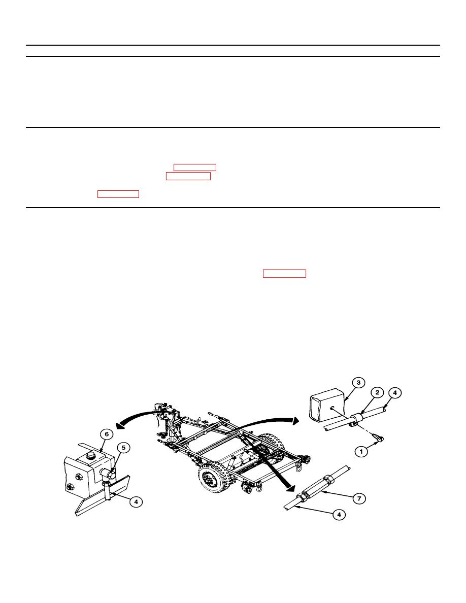
Remove five screws (1) from five loop clamps (2) along curb-side drawbar (3).
2.
Disconnect front tube assembly (4) from connector (5) at master cylinder (6).
3.
Disconnect front tube assembly (4) from coupling (70. Remove front tube assembly from curb-side drawbar.
4.
Remove five loop clamps (2) from front tube assembly (4).
|
|
Privacy Statement - Press Release - Copyright Information. - Contact Us |
