 |
|||
|
|
|||
|
Page Title:
HYDRAULIC BRAKE ACTUATOR ASSEMBLY REPLACEMENT (CONTINUED) |
|
||
| ||||||||||
|
|
 TM 9-2330-202-14&P
4-38.
HYDRAULIC BRAKE ACTUATOR ASSEMBLY REPLACEMENT (CONTINUED).
3.
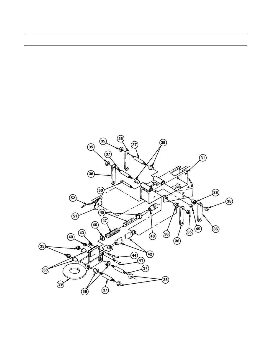
Remove eight self-locking nuts (35), four links (36) and shafts (37), eight bearings (38), and drawbar
coupler (39) from channel (31). Discard self-locking nuts.
4.
Remove self-locking nut (40), capscrew (41), and shock absorber (42) from drawbar coupler (39).
Discard self-locking nut.
NOTE
Boot may be in master cylinder.
5.
Remove self-locking nut (43) and socket head screw (44) from drawbar coupler (39) and pushrod
(45). Remove washer (46), spring (47), pushrod (45), and boot (48) from drawbar coupler (39).
Discard self-locking nut.
6.
Remove self-locking nut (49), capscrew (50), and breakaway lever (51), with chain (52) from channel
(31). Discard self-locking nut.
7.
If damaged, remove chain (52) from breakaway lever (51).
438-083
|
|
Privacy Statement - Press Release - Copyright Information. - Contact Us |