 |
|||
|
|
|||
|
Page Title:
HYDRAULIC BRAKE ACTUATOR ASSEMBLY REPLACEMENT |
|
||
| ||||||||||
|
|
 TM 9-2330-202-14&P
HYDRAULIC BRAKE ACTUATOR ASSEMBLY REPLACEMENT.
This Task Covers:
b. Disassembly
a.
Removal
d. Assembly
c.
Cleaning and Inspection
e.
Installation
Initial Setup:
Tools/Test Equipment:
Solvent, drycleaning (Item 15, Appendix F)
Lockwasher (4), 210104-8S
General mechanic's tool kit (Item 1, Appendix B)
Self-locking nut (8), MS21044N8
Common No. 1 tool set (Item 2, Appendix B)
Self-locking nut, MS21083-C7
Materials/Parts:
Self-locking nut (3), MS51922-21
Brush, wire (Item 2, Appendix F)
Self-locking nut (6), MS51922-29
Detergent (Item 5, Appendix F)
Self-locking nut (3), MS51922-61
Rag (Item 13, Appendix F)
a.
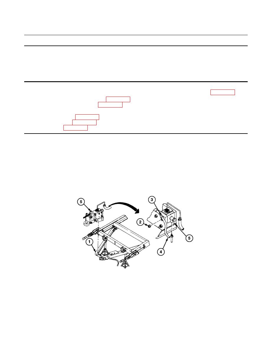
REMOVAL
1.
Place jackstand under drawbar (1) at each front corner of frame.
2.
Remove self-locking nut (2) and loop clamp (3), with intervehicular cable (4) from hydraulic brake
actuator assembly (5). Discard self-locking nut.
NOTE
Use a suitable container to catch any draining brake fluid. Make sure all spills are
cleaned up.
438-079
|
|
Privacy Statement - Press Release - Copyright Information. - Contact Us |
