 |
|||
|
|
|||
|
|
|||
| ||||||||||
|
|
 TM 9-2320-360-20-2
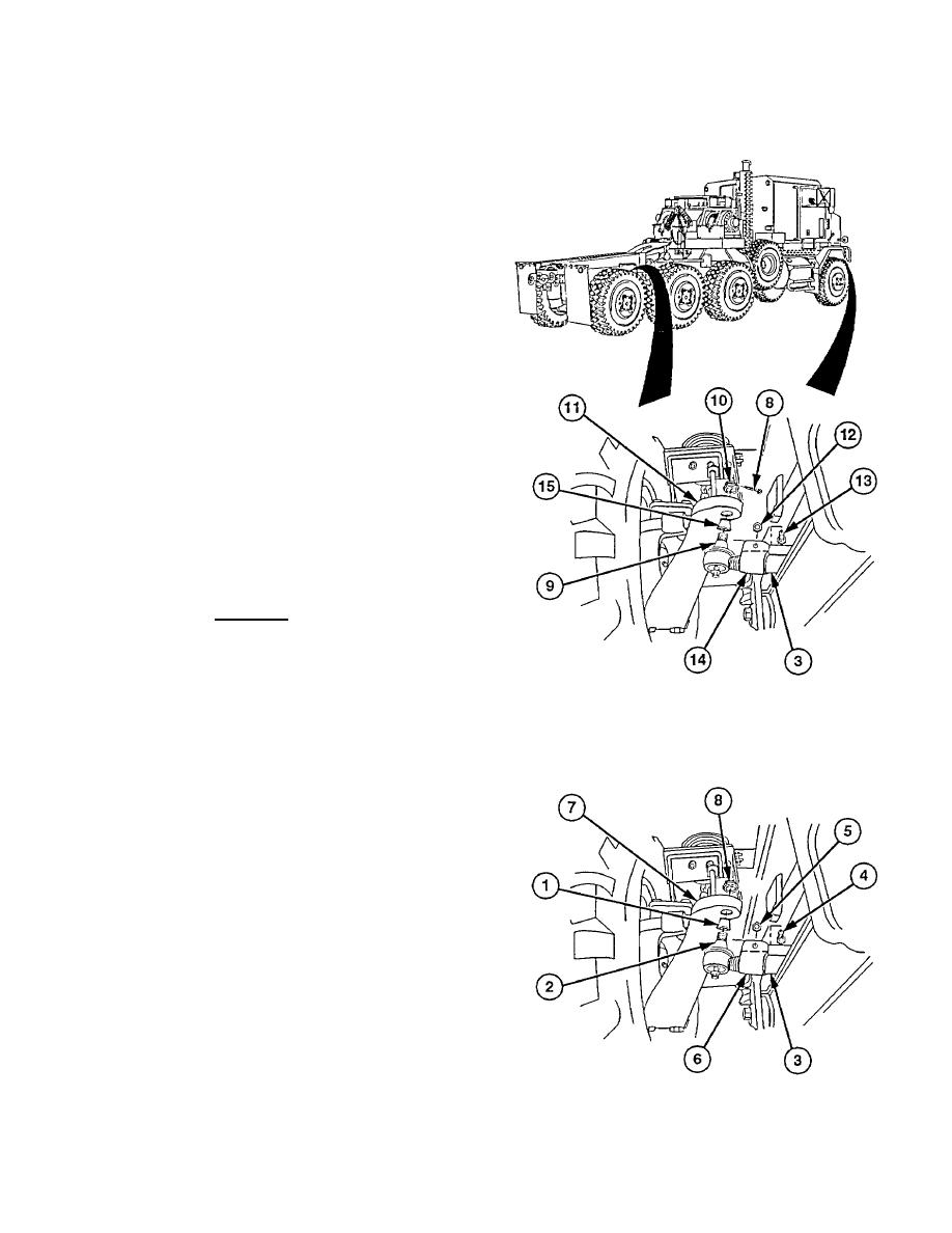
(3) Remove cotter pin (8) from tie rod end (9)
Discard cotter pin.
(4)
Remove castle nut (10) from tie rod end (9)
CAUTION
Nut must be installed upside down
on tie rod end. Failure to comply
may result in damage to nut.
(5)
Install castle nut (10) on tie rod end (9).
(6) Strike tie rod end (9) to loosen from steering arm
(11).
(7) Remove castle nut (10) from tie rod end (9).
(8) Remove locknut (12) and screw (13) from clamp
(14). Discard locknut.
(9)
Remove tie rod end (9) from tie rod (3).
(10)
Remove dust cover (15) from tie rod end (9).
b. Installation
(1)
Install dust cover (1) on tie rod end (2).
WARNING
Tie rod end must be threaded into tie
rod so that threads are beyond slot
under clamp. Failure to comply may
result in tie rod end separating from
tie rod resulting in loss of vehicle
control.
NOTE
Ensure tie rods are installed evenly
on tie rod ends.
Initial distance between tie rod end
grease fittings should be 61.5 in.
(156 cm) for no. 1 axle tie rod and
59.6 in. (151 cm) for no. 4 axle tie
rod.
(2) Install tie rod end (2) on tie rod (3).
(3) Install screw (4) and new locknut (5) on clamp
(6).
(4) Install tie rod ends (2) in steering arm holes (7)
with aid of assistant.
(5) Install castle nut (8) on tie rod end (2). Do not
tighten.
(6) Repeat step (5) for other end tie rod.
13-7
|
|
Privacy Statement - Press Release - Copyright Information. - Contact Us |
|
|
Integrated Publishing, Inc. - A (SDVOSB) Service Disabled Veteran Owned Small Business
|

