 |
|||
|
|
|||
|
|
|||
| ||||||||||
|
|
 TM 9-2320-360-20-2
c. Adjustment
NOTE
If boot has already been removed,
begin with step (5).
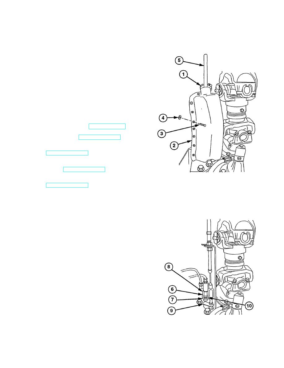
(1) Remove clamp (1) from boot (2).
(2) Cut seven ratchet fasteners (3) above
washers (4).
(3) Remove fasteners (3) and washers (4)
from boot (2). Discard fasteners.
(4) Remove boot (2) from shift cable (5).
(5) Start engine and build up air pressure to 110-
120 psi (758-827 kPa) (TM 9-2320-360-10).
(6) Shut off engine (TM 9-2320-360-10).
(7) Turn ENGINE switch to ON position
(TM 9-2320-360-10).
(8) Place DRIVELINE control in UNLOCK
position (TM 9-2320-360-10).
(9) Place TRANSFER CASE lever in LOW
(TM 9-2320-360-10).
NOTE
If all wheel drive indicator lights,
adjustment is correct. Go to step
(13).
If all wheel drive indicator light
fails, do steps (11) and (12).
(10) Check if all wheel drive indicator lights
(TM 9-320-360-10).
CAUTION
Actuator lever must not bottom out
on push valve. Failure to comply
may result in damage to push valve.
(11) Loosen nuts (6 and 7) on push valve (8).
Move valve (8) toward actuator lever (9)
through hole in bracket (10).
(12) Tighten nuts (6 and 7) and test again for
proper operation.
(13) Check for air leaks at push valve (8).
9-19
|
|
Privacy Statement - Press Release - Copyright Information. - Contact Us |
|
|
Integrated Publishing, Inc. - A (SDVOSB) Service Disabled Veteran Owned Small Business
|

