 |
|||
|
|
|||
|
|
|||
| ||||||||||
|
|
 TM 9-2320-269-34-1
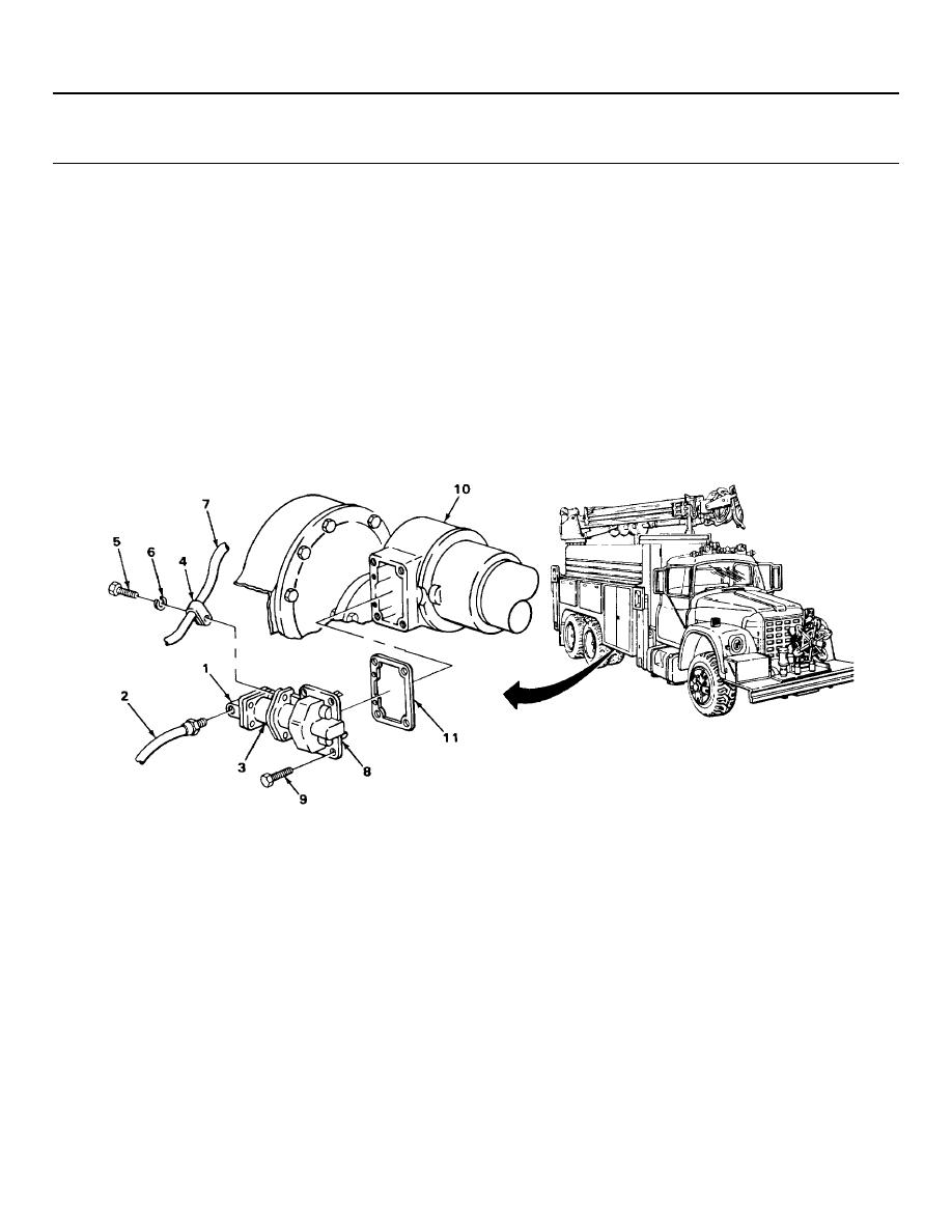
POWER DIVIDER LOCKOUT ASSEMBLY - CONTINUED
ACTION
LOCATION
ITEM
REMARKS
REMOVAL
NOTE
If tandem axle assembly or differential has been removed, skip steps 1 thru 3 and begin removal at step 4.
1.
Shift cylinder
Hose assembly (2)
Using 7/8-inch open-end wrench, unscrew
cover (1)
and take out.
2.
Shift cylinder body
Screw (5) and
a. Using 9/16-inch open-end wrench,
(3) and hose
lockwasher (6)
unscrew and take out.
clip (4)
b. Get rid of lockwasher (6).
3.
Shift cylinder
Hose clip (4) with
Move away from.
body (3)
hose assembly (7)
4.
Shift fork
Six screws (9)
Using 9/16-inch deep well socket and
housing (8)
ratchet handle with 3/8-inch drive, un-
screw and take out.
5.
Intermediate differ-
Shift fork housing
a. Take off.
ential case (10)
(8) and gasket (11)
b. Get rid of gasket (11).
2-898
|
|
Privacy Statement - Press Release - Copyright Information. - Contact Us |
