 |
|||
|
|
|||
|
|
|||
| ||||||||||
|
|
 TM 9-2320-269-34-1
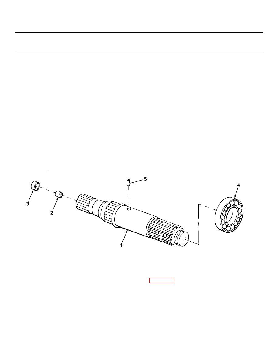
REAR COVER AND OUTPUT SHAFT - CONTINUED
ACTION
LOCATION
ITEM
REMARKS
ASSEMBLY - CONTINUED
41.
Output shaft (1)
Cap plug (2)
Using orifice plug installer and ball-peen
hammer, tap into place.
42.
Roller bearing (3)
a.
Position numbered end of bearing
towards installer.
b.
Using rear bearing installer, driver
handle, and ball-peen hammer, tap into
position.
Bearing should be 0.270 - 0.290-
inch (6.86 - 7.37 mm) below face
of bore.
43.
Output shaft
a.
Position bearing with chamfered edge
ball bearing (4)
of bore toward shoulder of shaft (1).
b. Using output shaft bearing installer
and arbor press, press against shaft
(1) shoulder.
44.
New spring pin (5)
Using an arbor press, press in 0.1 -
0.170-inch (3.81 - 4.31 mm) above shaft
surface.
NOTE
The output shaft, speedometer drive gear, governor drive gear, and spacer will be
installed when transmission is assembled.
FOLLOW-ON MAINTENANCE: Install rear cover (page 2-650).
TASK ENDS HERE
TA238473
2-778
|
|
Privacy Statement - Press Release - Copyright Information. - Contact Us |
