 |
|||
|
|
|||
|
|
|||
| ||||||||||
|
|
 TM 9-2320-269-34-1
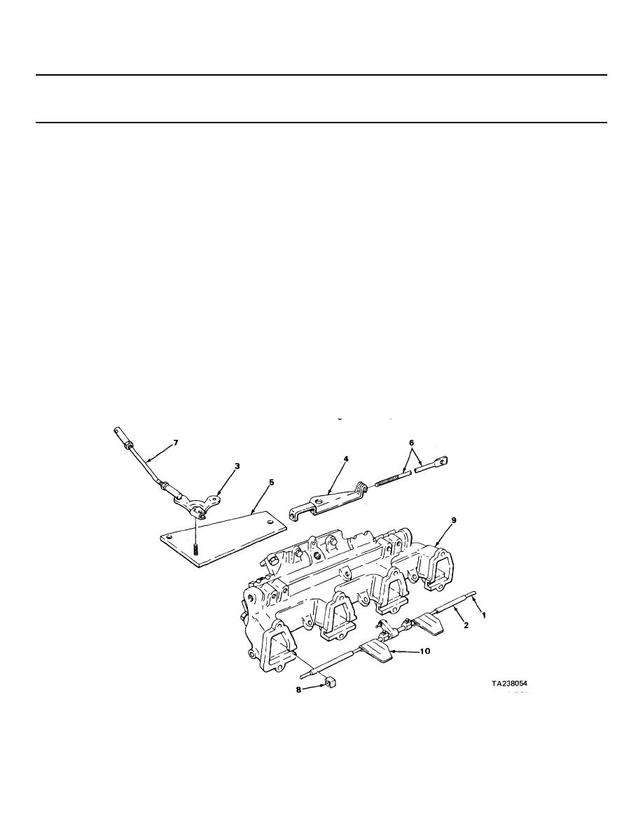
SWIRL DESTROYER - CONTINUED
ACTION
LOCATION
ITEM
REMARKS
ASSEMBLY
24.
Shaft assembly (1)
Two sleeve
Slide on.
spacers (2)
25.
Six rubber
Put on, split facing up.
bushings (8)
Note that four bushings have larger
inside diameter and are used over
sleeves, while two bushings have
smaller inside diameter and are used
directly on the shaft, at the middle.
26.
Intake manifold (9)
Shaft assembly (1)
a. Put in place.
with bushings (8)
b. Turn shaft (1) so that plates (10) are
in closed position and touch side of
manifold (9).
c. Using thickness gage, measure clear-
ance between plate (10) and mani-
fold (9).
Clearance should be 0.005 inch
(0.12 mm).
d. If clearance is not 0.005 inch
(0.12 mm), do step 27.
e. If clearance is within tolerance given,
qo on to step 28.
2-241
|
|
Privacy Statement - Press Release - Copyright Information. - Contact Us |
