 |
|||
|
|
|||
|
Page Title:
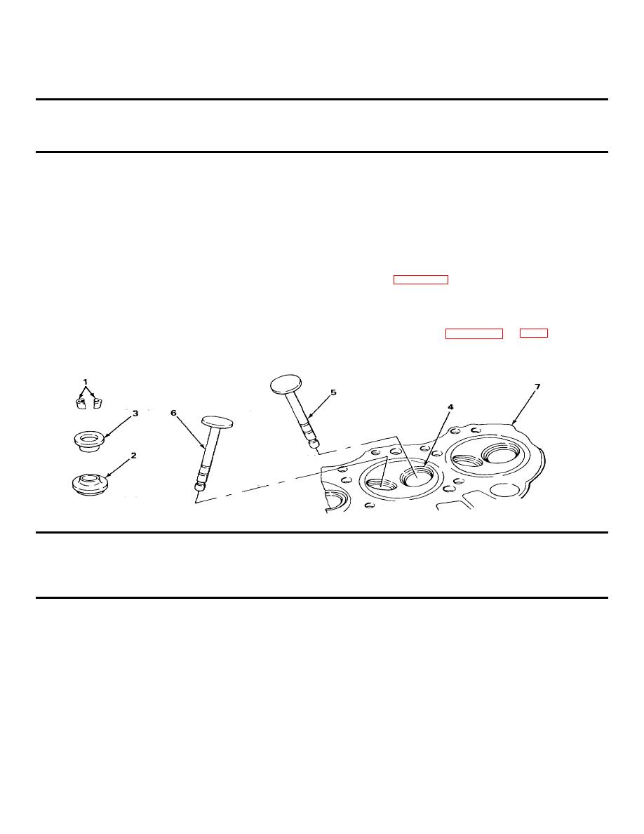
INSPECTION/REPLACEMENT/REPAIR - CONTINUED |
|
||
| ||||||||||
|
|
 TM 9-2320-269-34-1
INTAKE AND EXHAUST VALVES - CONTINUED
ACTION
LOCATION
ITEM
REMARKS
INSPECTION/REPLACEMENT/REPAIR - CONTINUED
8. Continued
d.
Rotate valve (5) or (6) one complete
revolution.
e. Take out valve (5) or (6), and check
insert (4) for low spots.
Low spots will not have any pencil
mark showing.
f. If valve seat insert (4) requires re-
placement see Cylinder Head Repair
g. If inspection shows valve (5) or (6) and
valve seat insert (4) need to be ground,
or new part is used, send cylinder
head (6) with valves (5) or (6), with
Table IV-1. (pages 2-161 and 2-162) to
machine shop.
TABLE IV-1
INTAKE AND EXHAUST VALVE SPECIFICATIONS
INTAKE VALVES
Valve lift
0.455 in (11.56 mm)
Stem diameter
0.3725 - 0.3730 in (9.461 - 9.474 mm)
Clearance in guide
0.0008 - 0.0023 in (0.020 - 0.054 mm)
O
Face angle
45
O
Seat angle
45
Seat width
0.080 - 0.090 in (2.03 - 2.29 mm)
TA238007
2-161
|
|
Privacy Statement - Press Release - Copyright Information. - Contact Us |
