 |
|||
|
|
|||
|
Page Title:
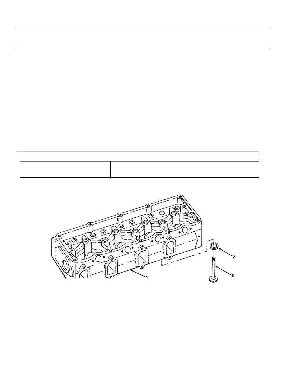
INTAKE AND EXHAUST VALVE SEAT INSERTS |
|
||
| ||||||||||
|
|
 TM 9-2320-269-34-1
CYLINDER HEADS - CONTINUED
ACTION
LOCATION
ITEM
REMARKS
REPAIR - CONTINUED
22.
Cylinder head (1)
Valve seat insert
j
Using dial indicator, check insert (2)
Continued
(2) and valve (3)
for runout.
Maximum runout allowed for Intake
and exhaust valve seat Inserts Is
0.002 inch (0.05 mm).
k. To check valve face contact, apply thin
coat of Prussian blue on respective
valve (3) (location noted during
removal).
I
Position valve (3) in cylinder head (1),
and using soft plastic-face hammer, tap
lightly to seat.
m. Take out valve (3).
n. Note markings on insert, and make
necessary corrections so that seat
dimensions given below are met.
o. When seat contact is satisfactory, mark
each valve (3) for installation.
INTAKE AND EXHAUST VALVE SEAT INSERTS
FACE ANGLE
45 degrees
SEAT ANGLE
45 degrees
SEAT WIDTH
0.080 - 0.090 inch (2.03 - 2.29 millimeter)
TA237975
2-110
|
|
Privacy Statement - Press Release - Copyright Information. - Contact Us |
