 |
|||
|
|
|||
|
Page Title:
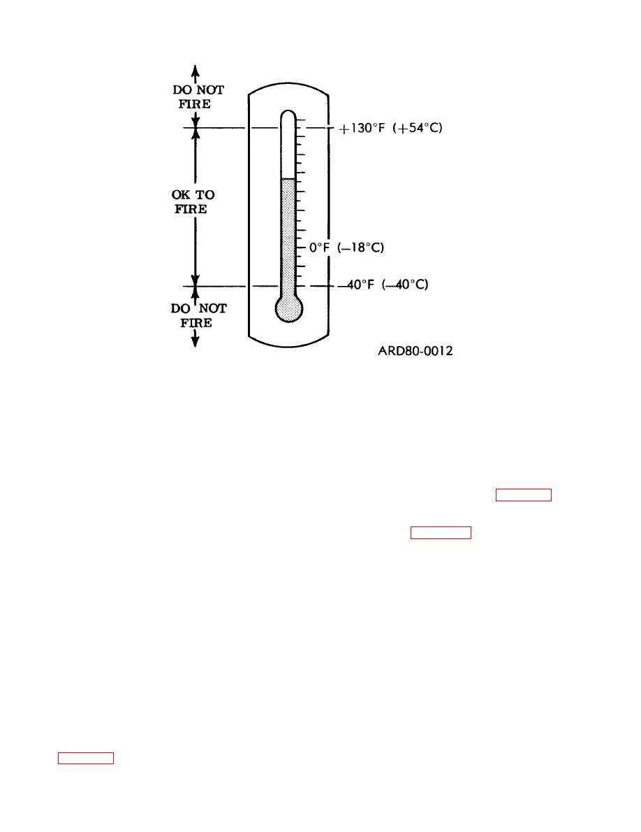
Figure 2-1. Temperature firing limits. |
|
||
| ||||||||||
|
|
 TM 9-1375-213-12-1
Figure 2-1. Temperature firing limits.
temperatures the kit's temperature will
(b) In an airfield pocking operation, the
be close to that of the area where it has
orientation cited in b (1) (a), above is not required
been located for an hour or two. At high
since the main objective is to create many holes
temperatures, the sun can quickly raise
in the airfield runways, with no particular regard
the temperature of an exposed kit or an
to direction.
enclosed shelter (such as a box-car) far
(2) Road cratering. Road widths that can be
higher than that of the outside air. A good
successfully cratered by a single kit or by several
rough method of determining whether a
closely spaced kits are indicated in figure 2-2. No
kit is too hot to fire is to (carefully) touch
more than five kits may be fired at once in close
the surface of the rocket motor. If you can
multi-kit deployment, and only the deployment
keep your hand on the surface without
setups shown in figure 2-2 may be used. Any
discomfort, the kit is cool enough to fire.
other spacings or orientations may reduce the
effectiveness of the shot.
(1) General.
(3) Airfield pocking. In operations such as air-
(a) Because the shaped charge and rocket
field pocking, up to 15 kits may be fired simulta-
propelled warhead are aimed at a 60 angle to the
neously if there is a minimum of 25 feet (7.5 me-
ground, the resulting crater will tend to have a
ters) between kits.
steeper slope on the side toward which the launch
leg is aimed. Therefore, when kits are being used
2-4. Initial Preparations
to make a vehicle obstacle, the steeper side should
be oriented so as to make exit more difficult in
a. Unless otherwise noted, the following para-
the anticipated direction of enemy travel. When
graph refers to single kit and multi-kit operations.
the steeper side lies at an angle to the road (rather
(1) Determine number of kits to be used and
than straight across the road), vehicle movement
method of deployment (b above).
will be further hindered in that the vehicle will
(2) Select a suitable location for the firing site
be channeled off the roadway in its attempts to
(no closer than 500 feet (150 meters) if there is
back up the shallowest slope of the crater. To ob-
cover, or 4000 feet (1200 meters) if there is no
tain the most effective vehicle obstacle, the de-
cover).
ployment angles and placement of the kits shown
(3) Mark target point for each kit that is to be
in figure 2-2 must be stictly adhered to.
used.
2-2
|
|
Privacy Statement - Press Release - Copyright Information. - Contact Us |
