 |
|||
|
|
|||
|
Page Title:
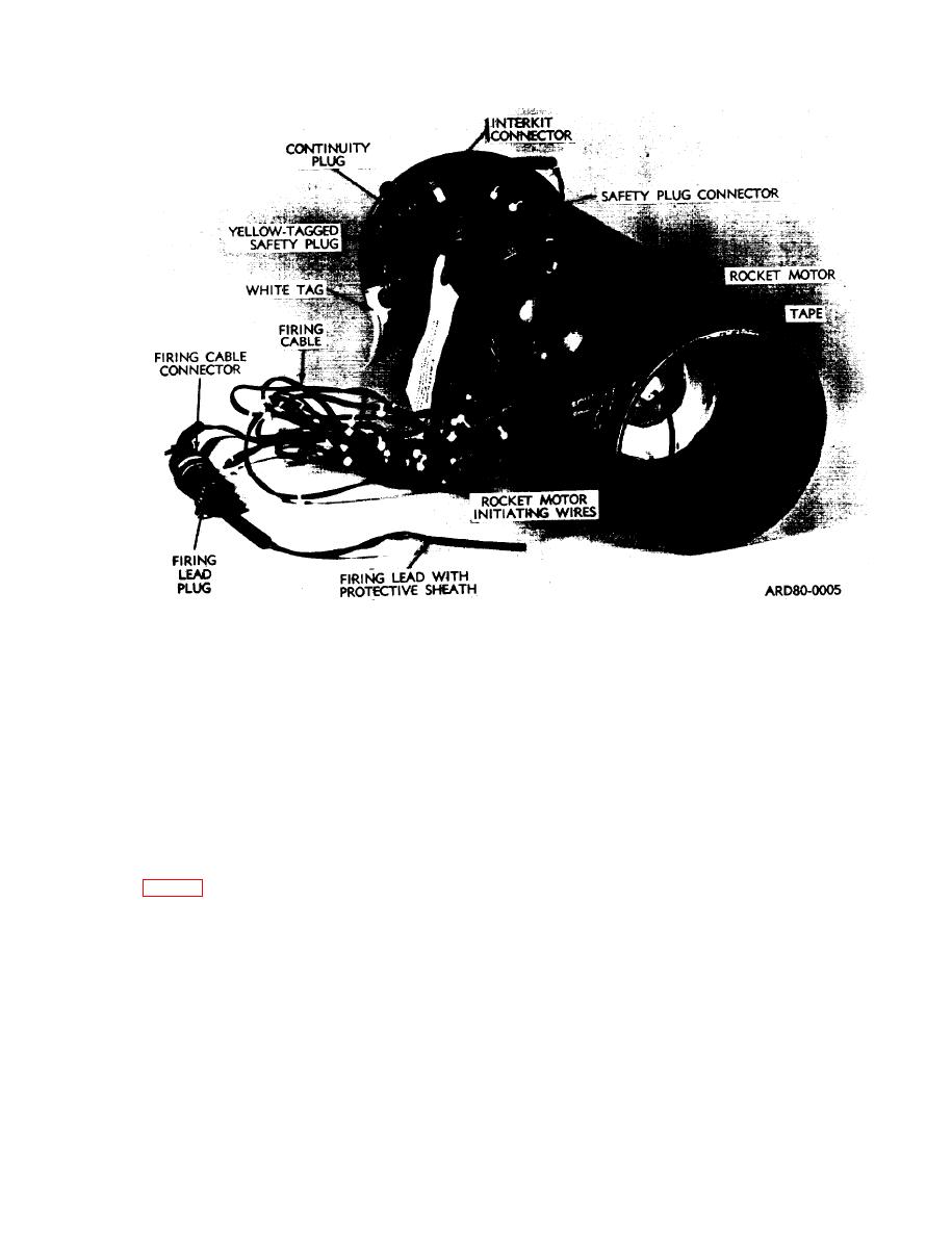
Figure 1-5. Rocket motor, rear view. |
|
||
| ||||||||||
|
|
 TM 9-1375-213-12-1
Figure 1-5. Rocket motor, rear view.
their conduit to the delay blasting cap in the
(2) Each rocket motor has a permanently at-
booster.
tached firing circuit which is electrically wired to
6. A yellow-tagged safety plug is con-
permit initiation as a single kit or as a part of a
nected to the safety plug connector and a white
series circuit when a number of kits are employed
tagged continuity plug is connected to the interkit
together.
connector.
(a) The circuit consists of a firing lead (with
protective sheath and firing lead plug), 10-foot
NOTE
(300 centimeters) firing cable with firing cable
To remove the safety plug, just pull it out
connector, rocket motor initiating wire, detonator
of its connector. The outer collar on the
wires, safety plug connector and interkit connec-
safety plug is NOT threaded. It is free to
tor (fig. 12).
rotate but does not touch the safety
1. The firing lead is used to splice the fir-
plug's mating connector. To insert the
ing circuit to the field firing lead.
safety plug in its connector hold it by its
2. The firing lead plug is connected to the
body (not its outer collar) and turn it so
firing cable connector.
that its notch aligns with the mating
3. The firing cable ends in a junction con-
guide pin in the connector and push in.
sisting of the wires for the rocket motor initiating
(b) The yellow-tagged safety plug prevents
wires, detonator wires, safety plug connector, and
firing of the kit and must be removed in either
interkit connector.
the single or multi-kit hookup. The continuity
4. The rocket motor initiating wires are
plug must be installed in the interkit connector
taped to the outside and inside edge of the nozzle
in order to fire a single kit. In order to fire a multi-
and connect to the M2 squibs in the rocket motor
kit hookup, the kits must be installed in a single
initiator.
5. The detonator wires are routed through
series circuit as follows:
1-7
|
|
Privacy Statement - Press Release - Copyright Information. - Contact Us |