 |
|||
|
|
|||
|
|
|||
| ||||||||||
|
|
 TM 9-1300-277
(2) All connections between blasting cap
wires, connecting wires, and firing wires are properly
made (par 5-10e).
(3) The number of blasting caps in any circuit
does not exceed the rated capacity of the blasting
machine being used.
c. Connect the blasting machine by untwisting the
ends of the firing wire and fastening them to the two
posts of the blasting machine.
d. Fire the blasting machine using one of the
following methods (table 5-1):
(1) Ten-cap blasting machine:
(a) Insert hand through strap (if
attached).
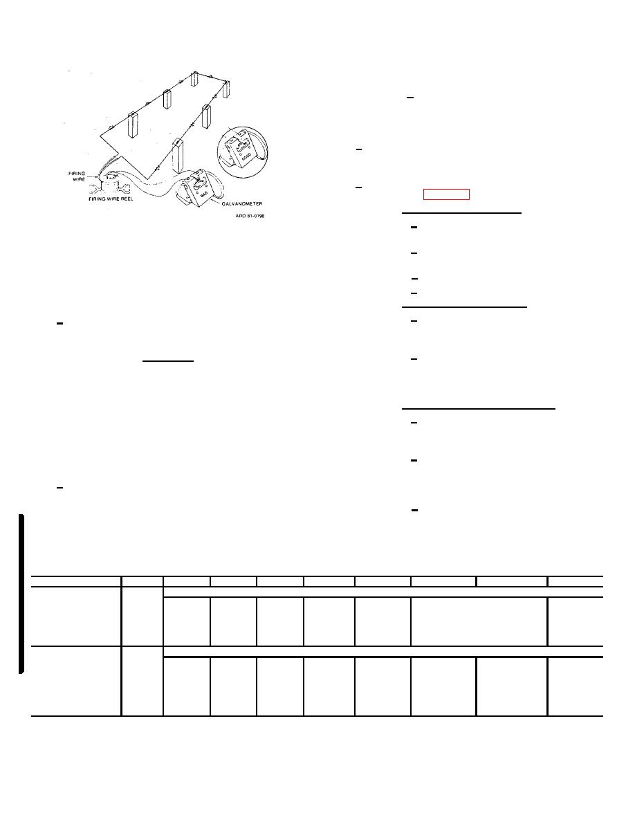
Figure 5-14. Testing firing circuit.
(b) Grasp the bottom of the blasting
machine.
5-11. BLASTING MACHINE
(c) Insert the handle.
(d) Twist vigorously.
The blasting machine will be test-operated,
(2) Fifty-cap blasting machine:
attached, and fired in accordance with the following:
(a) Set machine squarely on a solid,
a. Test operate the blasting machine by actuating
level place and lift plunger by handle to its maximum
several times with nothing attached to the terminals.
extension.
(b) With body well balanced, feet wide
WARNING
apart, and in a partially stooped position, grasp handle
DO NOT CONNECT THE BLASTING
firmly with both hands and push plunger down with a
MACHINE TO THE FIRING WIRES
quick, hard stroke.
UNTIL AILL PREFIRING TESTS HAVE
(3) M32 and M34 blasting machines:
BEEN COMPLETED AND UNTIL A
(a) Release blasting machine handle by
SIGNAL IS RECEIVED FROM THE
rotating O-ring with handle springs outward from body of
SUPERVISOR THAT THE AREA HAS
machine.
BEEN
CLEARED
OF
ALL
(b) Hold machine in upright position
PERSONNEL AND EQUIPMENT.
(terminals up) in either hand so that the plunger end of
handle rests under base of thumb and fingers grasp
b. To prevent a misfire, ensure that the following
machine body.
have been accomplished prior to firing the blasting
(c) Squeeze hand sharply several times
machine.
in succession until charge fires. Not more than four
(1) All blasting caps are included in the firing
strokes should be required.
circuit.
Table 5-1. Maximum Circuit Capacities of Various Power Sources
1
2
3
4
5
6
7
8
9
10
Total
Power source
number
1 -kw
3-kw
5-kw
3-kw
5-kw
of caps
10-cap
30-cap
50-cap
portable
portable
portable
portable
portable
Circuit design
in
blasting
blasting
blasting
generator
circuit
machine
machine
machine
115-volt,
115-volt
115-volt
220-volt
220-volt
13 amp
26-amp
43 -amp
13 -amp
22 amp
The circuits below are connected by one 500-foot standard two-conductor firing reel
10 caps in continuous
10
X
X
X
X
X
X
X
X
series.
30 caps in continuous
30
----
X
X
X
X
X
X
X
series.
series.
50 caps in continuous
50
----
----
X
----
----
----
X
X
Change 2
5-12
|
|
Privacy Statement - Press Release - Copyright Information. - Contact Us |