 |
|||
|
|
|||
|
Page Title:
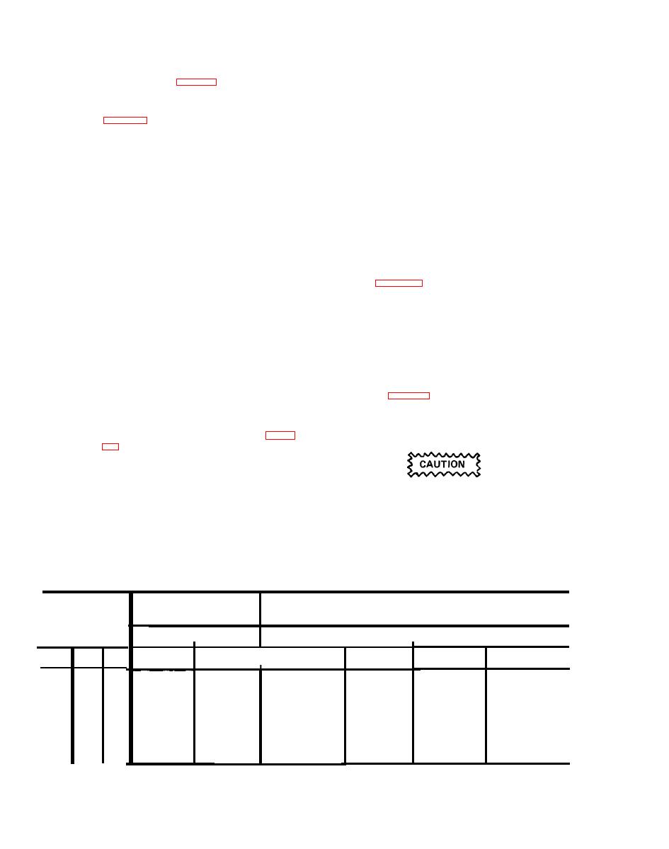
Table 5-7. Indicated Airspeed Calibration Check. |
|
||
| ||||||||||
|
|
 TM 9-1270-219-13&P
sure to generate a Test Set numeric readout
S u p p l y Test (see Fig. 1-32).
e. L A I
Power
value of 207 units (equivalent pressure of
1 7 5 knots) and isolate the EPU under test
(1)
Connect
the
EPU
for
test
as
shown
in
from the Tester, Pitot Static Systems. Start
the stopwatch and check that the DATA
WORD display on the Test Set does not
S e t test set switch S10 OUTPUT SEL 2 to
(2)
c h a n g e by more than 5 units in 3 minutes.
LAI +15V. Using the Digital Voltmeter set
to dc volts check that the voltage between
Open the tank vent valve to relieve the pres-
(4)
test points 7 (+ve) and 8 on the Test Set is
sure and disconnect the pressure equipment.
+15V 1.0V.
leak
test
pitot
pressure
Disconnect
(5)
S e t test set switch S10 OUTPUT SEL 2 to
(3)
equipment.
LAI -15V. Using the Digital Voltmeter set
to dc volts check that the voltage between
g. Indicated Airspeed Calibration Check.
test points 7 (+ve) and 8 on the Test Set is
(1)
Connect
the
EPU
for
test
as
shown
in
15v1.0.
f. Pitot Pressure Leak Test.
(2) Set test set switch S7 RDR ALT FT to 30.
NOTE
(3) Using the Digital Voltmeter set to dc volts,
check the voltage between test points
Leak tests for the EPU are perfomed by
7
(+ve)
and
8
on
the
Test
Set
for
the
monitoring leak rates on the Test Set
positions of the test set switches and the
DATA
WORD
display,
therefore
it
is
manometer
pressure
settings
as
detailed
essential that the pressure source (Tester,
in Table 5-7.
P i t o t Static Systems) is isolated prior to
monitoring the leak rate.
(4)
Return
the
applied
pressure
slowly
to
and
disconnect
ambient
the
pressure
(1) Connect the EPU for test as shown in figures
equipment.
( 2 ) Set test set resolver dials B1 and B2 to 0.
S e t test set switch S8 DATA WD SEL TO
R e s o l v e r s B1 and B2 must be positioned
V u. Set S6 AIR TEMP. to 0.
to 0 via the shortest route to prevent an
ADS fail being generated.
(3) Close the tester pitot vent valve and open
(5)
On
completion
of
the
test,
set
test
set
the tester pressure source valve. Close the
resolvers B1 and B2 to 0.
tank vent valve. Apply sufficient pitot pres-
Analog
Test Set Resolver
IAS Outputs S10
Dial Setting
Pressure
Input
V
Volts
Volts
V
B2
B1
IU
IU
IN
IN
Knots
Nominal
Tol.
Tol.
Deg.
Nominal
Deg.
H 2O
Hg
+0.70
+0.61
0.30
0.6
0.04
30
0.40
60
80
0.40
0.30
+0.72
1.81
120
130
0.8
0.06
35
0.40
1.35
0.30
100
+0.16
35
0.8
0.06
70
0.40
0.30
1.11
+1.74
40
40
1.0
0.08
50
0.40
+5.00
0.30
55
2.0
0.15
25
0.84
20
|
|
Privacy Statement - Press Release - Copyright Information. - Contact Us |
