 |
|||
|
|
|||
|
Page Title:
Section IV. REPAIR OF ELECTRONIC INTERFACE ASSEMBLY (EIA) |
|
||
| ||||||||||
|
|
 TM 9-1270-212-14&P
Section IV. REPAIR OF ELECTRONIC INTERFACE ASSEMBLY (EIA)
f. Assemble items
(12)
through
(2)
in
revers
disassembly sequence.
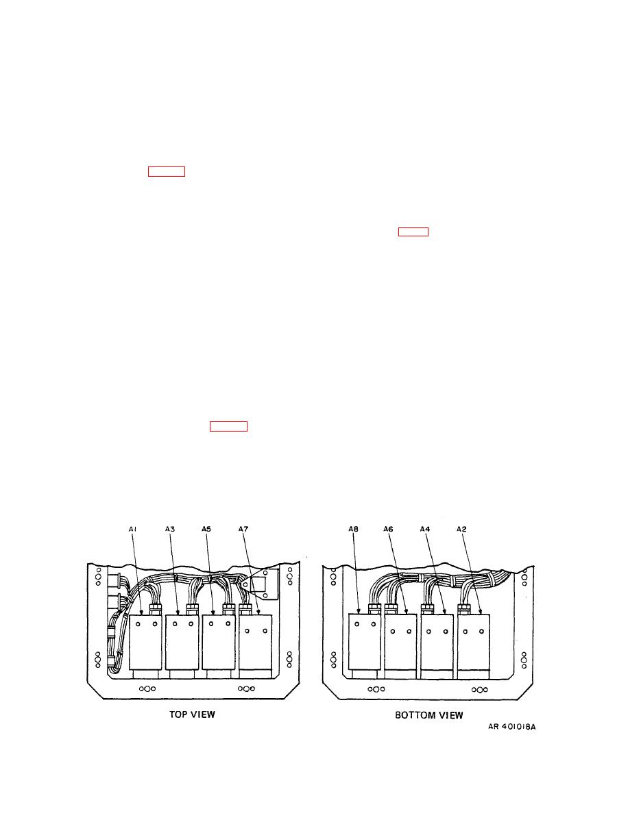
b. Slice the circuit card extractor handle over the top
Assembly.
lugs of each of circuit cards A12 (13), A13 (14), A11 (15),
A10/A15 (16), and A9 (17) and remove the card by pulling
a. XM128 EIA (fig. 5-5).
it straight out.
(1) Remove items (1) through (72), except items (6),
(7), (8), (24), (27), (33), (40), (57), (58), (66), (67), and
(69). Unsolder and mark leads where necessary.
When loosening the connector hold screws on
NOTE
the buffer-amplifier cable connectors, take care
Resistors R9 and R10 mounted on TB1 (56)
to prevent damage to the cable harness.
and resolver B1 (33) are a matched set. The
c. Remove items (18) through (21).
resistors are furnished with the resolver.
(2) Carefully break the adhesive that anchors the
wire bundles to the replaceable components.
including flat washer (20), lockwasher (19), and screw (18),
as illustrated in figure 54.
(3) Assemble items (72) through (1) in revers
disassembly sequence.
c. Assemble circuit cards A9 ( 17, fig. B-10), A10/A15
(16), A11 (15). A13 (14), and A12 (13) by sliding the cards
(4) Verify that replacement transformer T2 (16) has
down the teflon guide and into the mating connector. The
a soft-tempered, coated, AWG 24, uninsulated, solid bus
cards are keyed and marked to insure proper placement and
wire, conforming to QQ-W-343, between terminals 2 and 3.
should be firmly pressed into the mating connector.
|
|
Privacy Statement - Press Release - Copyright Information. - Contact Us |
