 |
|||
|
|
|||
|
Page Title:
Section III. REPAIR OF LINKAGE ASSEMBLIES (GUNNER AND PILOT) |
|
||
| ||||||||||
|
|
 TM 9-1270-212-14&P
Section III. REPAIR OF LINKAGE ASSEMBLIES (GUNNER AND PILOT)
b. Remove two spring pins ( 12) by placing aft support
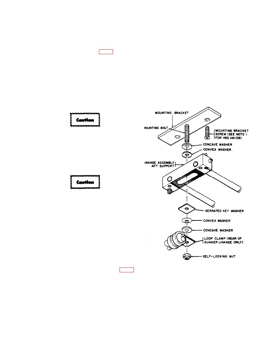
5-13. Removal of Linkage Assemblies (fig. 5-3).
(13) on a block and driving spring pins out with a 5/32 drift
pin.
a. Place the linkage arm assembly in the stow position
(fig. 2.10).
c. Remove rails (14) from arm assembly (15).
b. Loosen the captive screws and disconnect the cable
d. Assemble in reverse disassembly sequence. Place rails
connect or.
(14) in aft support (13) so that the grooves in the rails line
up with the spring-pin holes. Drive. in new spring pins (12)
c. Remove the self-locking nut, concave washer, convex
so that the slots on the pins are opposite the grooves in the
washer, and key washer that secure the front support to the
rails.
bracket.
The front end of the linkage assembly must be
supported while the mounting hardware is
removed from the aft support.
d. Remove the self-locking nut. concave washer. convex
washer. loop clamp (gunner linkage only), and key washer
that secure the aft support to the bracket.
Do not tip the front end of the linkage
assembly down or the front support and arm
assembly will slide off the rails.
e. Carefully lower the assembly, two convex washers,
and two concave washers from the two brackets.
f. Remove the two brackets from the airframe by
removing four screws. Retain the screws.
g. If the assembly is not to be reinstalled in the
helicopter at this time, reverse steps c through e to
reassemble the assembly and avoid loss of hardware.
NOTES:
FOR HSS XM128, EXTENSION-CABLE BRACKET ASSEMBLY
1.
MUST BE INSTALLED AS SHOWN IN FIGURE 5-6.
NOTE
2. REMOVAL AND INSTALLATION AT FRONT AND AFT
SUPPORTS OF PILOT AND GUNNER LINKAGE ASSEMBLIES
Disassemble only items necessary to complete
ARE IDENTICAL EXCEPT THAT GuNNER-LINKAGE AFT
repair procedures.
SUPPORT HAS LOOP CLAMP.
AR 401076
a. Remove items (2) through (11).
|
|
Privacy Statement - Press Release - Copyright Information. - Contact Us |