 |
|||
|
|
|||
|
|
|||
| ||||||||||
|
|
 TM 9-1270-212-14&P
e. Apply a drop of sealing compound conforming to
MIL-S-22743, grade T (primer) and grade H, to the threads
of the shaft and nut. Install swivel nut (28) and tighten to
NOTE
a torque value of 5 inch-pounds with a torque wrench.
Disassemble only items necessary to complete
f. Tighten three setscrews (27) to hold magnet in
repair procedures.
position.
g. If a new magnet is installed, mark a spot in the epoxy
of magnet (29) closet to the white mark on receptacle (33).
b. Assemble in reverse order, referring to c through i.
h. Drill a 1/8-inch-diameter hole, 0.010 inch deep, in
the marked spot in the epoxy, being careful not to hit the
c. Assemble latch assembly (34) as shown.
magnet.
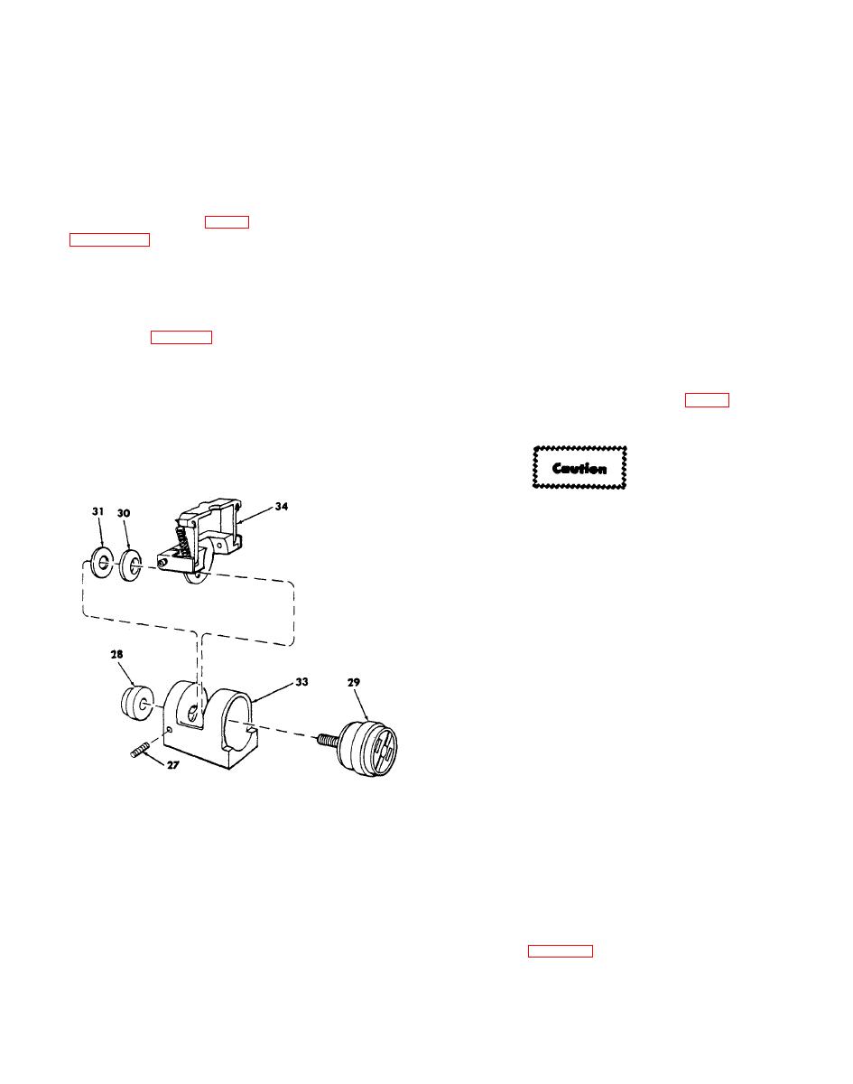
d. Refer to figure 5-2. Install setscrews (27) loosely so
i. Fill the hole with white epoxy conforming to
that they will not touch the shaft on magnet (29).
MS18038-91.
Assemble" convex washer (30), flat washer (31), latch
assembly (34), and magnet (29) into helmet receptacle
(33). Rotate the magnet to align the white dots. If a new
magnet is being installed, rotate the magnet so that
continuit y exists between A1Pl-5 and -6 with a linkage arm
assembly steel fastener (or the helmet boresight tool)
attached to the magnet (29) and so that an open circuit
exists when the steel fastener is disconnected.
Do not disturb or remove the flathead screw at
the falter-assembly (5) end of straight shaft (8).
The screw is a part of the filter assembly and is
bonded in place.
a. Remove items (1) through (14) and assemble
reverse order.
b. Apply a drop of sealing compound conforming to
MIL-S-22473, grade T (primer) and grade H, to bond the
cap (12) to the sight housing (36).
New SPH-4 Helmet (fig. 5-l).
NOTE
Installation items called out in this paragraph
are furnished with a new helmet sight assembly.
NOTE: FOR PROCEDURAL CLARITY AND FOR PURPOSES OF
THIS FIGURE ONLY, SPECIFIC ITEMS FROM FIGURE
B-2 ARE IDENTIFIED.
a. Remove the visor housing and visor from the helmet
AR 401075B
27 Setscrew (3)
by removing the four mounting screws and mounting nuts.
28 Swivel nut
29 Magnet
NOTE
30 Convex washer
31 - Flat washer
The visor housing will not be reinstalled and it
33 Helmet receptacle
and its mounting screws and mounting nuts do
34 Latch assembly
not appear on figure 5-1. Dispose of the visor
housing according to local instructions.
|
|
Privacy Statement - Press Release - Copyright Information. - Contact Us |
