 |
|||
|
|
|||
|
Page Title:
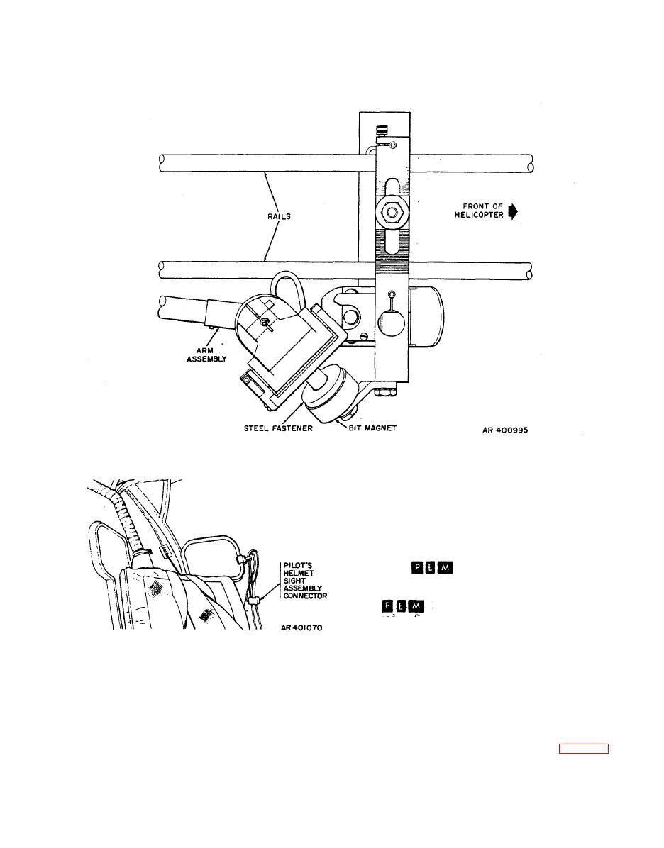
Figure 2-11. Linkage assembly - use of BIT position |
|
||
| ||||||||||
|
|
 TM 9-1270-212-14&P
NOTE
In the procedures below, where the nomencla-
ture of a control, control position, or indicator
differs between the AH-lS(Mod) and the
AH-1S
helicopters, the basic nomen-
clature used is that for the AH-IS(Mod) heli-
copter and the nomenclature for the AH-1S
helicopters follows, in parentheses
and prefixed with an "or;" for example, "HS
RTCL OFF BRT (or HSS RTCL OFF BRT)"
in a(4) below.
helmet sight assembly cable
a. Reparation of Pilot and Gunner Helmet Sights.
connections, and actuate the HSS BIT stitch again. If the
(1) The helmet sight assembly has a cable that
failure persists, perform the corrective action given in table
terminates in an eight-pin connector. Attach this connector
3-4.
to the connector jack on the side of the seat (pilot, left
side; gunner, right side) in the same clip as the
NOTE
communications connector, as shown for the pilot in figure
2-12.
A factory replacement linkage or arm installed
in an XM136 system will probably not pass a
(2) Put on the helmet, making sure it is positioned
BIT test until after boresighting is complete.
comfortably and the chin strap is securely fastened.
|
|
Privacy Statement - Press Release - Copyright Information. - Contact Us |
