 |
|||
|
|
|||
|
Page Title:
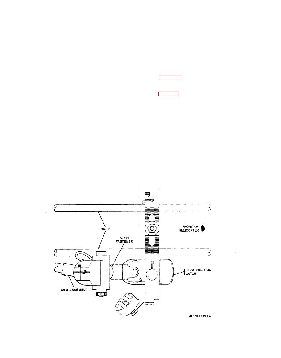
Figure 2-10. Linkage assembly - use of stow position |
|
||
| ||||||||||
|
|
 TM 9-1270-212-14&P
HS RTCL OFF BRT (or HSS RTCL OFF BRT) to
e. Check that the ELEC PWR EMER OFF switch on the
midpoint.
gunner left pedestal panel (or gunner's miscellaneous
panel), just forward of the collective stick, is set to ELEC
b. On the gunner armament control panel, set the
PWR.
switches as follows:
f. Press the stow position latches and remove the pilot
TURRET DEPR LIMIT (or LASER SAFE/TURRET
and gunner linkage arm assemblies from the stow brackets
DEPR LIMIT) to TURRET DEPR LIMIT
as shown in figure 2-10. Place the linkage arm assemblies in
the BIT stow positions by attaching the linkage arm
PLT OVRD (or PLT ORIDE) to OFF
assembly connectors to the magnetic BIT stow receptacles
as shown in figure 2-11.
HSS RETICLE OFF BRT (HSS RTCL OFF BRT or HSS
OFF BRT) to midpoint.
g. Set the MASTER ARM switch on the pilot armament
control panel to STBY.
c. Set the MODE SELECT switch on the TOW control
h. Press the ARMED STBY indicator on the pilot
panel to OFF.
armament control panel and the gunner armament control
panel and press the PLT GNR INTFC GO (or PLT GNR
d. On the electrical power control panel, set the
EIA GO) indicator on the gunner armament control panel.
switches as follows:
All sections of the indicator light.
INV to MAIN (or ALTNR to ON)
i. Allow 15 seconds for warmup, and then actuate the
HSS BIT switch on the gunner armament control panel.
BAT to ON (or BATTERY to RUN).
The GO indicator lights for 5 to 10 seconds. If a failure
indicator lights, insure that the linkage assemblies are
NON-ESS BUS (or NON-ESNTL BUS) to NORMAL.
properly attached to the BIT magnets, check all cable
|
|
Privacy Statement - Press Release - Copyright Information. - Contact Us |
