 |
|||
|
|
|||
|
Page Title:
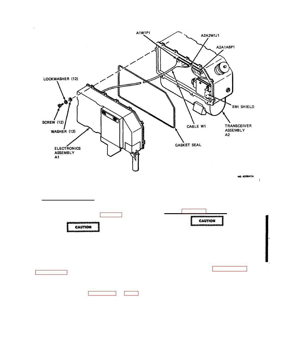
Figure 4-1. LD/R Assemblies Al and A2 |
|
||
| ||||||||||
|
|
 TM 9-1260-477-34
Figure 4-1.
LD/R Assemblies Al and A2
Installation (Fiqure 4-1).
b.
4-3.
CONTROL CARD A1A3 AND RESOLVER-TO-DIGITAL
CONVERTER A1A4 REPLACEMENT
(1) Lubricate exposed surface of gasket seal
a.
Removal (Figure 4-2, Sheet 1).
in A1 assembly with lubricant (28, Table B-1).
Control Card A1A3 and Resolver-to-Digital
Converter A1A4 are electrostatic sensitive.
Insure screws are torqued evenly one turn
Protect these cards by wearing grounding
at a time to avoid damaging connector.
wristband when probing.
Handling and/or
installation of individual cards should be
(2) Connect A1A1W1P1 to A2A2W1J1 and tighten
performed at a static-free work station.
two jackscrews evenly one turn at a time.
These cards should be anti-static packaged
jackscrews 5 to 6 inch-pounds.
during handling and storage.
(3) If A2 is replaced, perform PFN VDC adjustment
(1) Separate Al and A2 per paragraph 4-2.
per paragraph 2-11.
(4) Secure Al to A2 using 12 screws, lock-washers,
(2) Remove ten screws (17) and washers (18).
and washers. Torque screws 6 to 7 inch-pounds.
(5)
Purge
per
(3) Lift control card A1A3 (13).
4-2
|
|
Privacy Statement - Press Release - Copyright Information. - Contact Us |
