 |
|||
|
|
|||
|
Page Title:
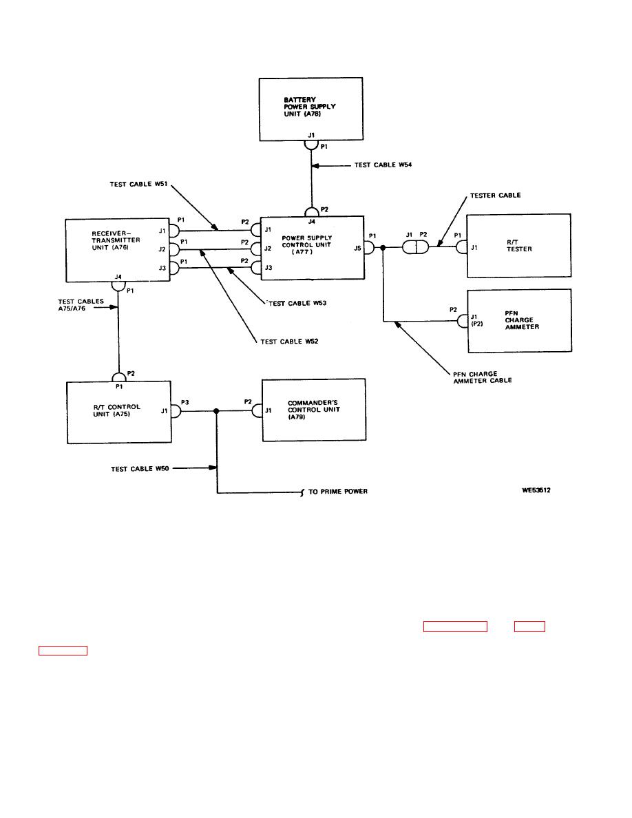
Figure 2-5. Hot mock-up interconnection diagram |
|
||
| ||||||||||
|
|
 TM 9-1240-369-34
Figure 2-5. Hot mock-up interconnection diagram.
Section II. TROUBLESHOOTING
support maintenance function is the PFN adjustment.
2-5. General.
Because of this adjustment, it is required that the
The troubleshooting procedures described in this
receiver-transmitter unit and power supply control unit be
section consist of fault isolation within the major units to
replaced as a pair. Schematic and wiring diagrams for
modules, printed circuit cards and assemblies, and their
the units of the laser range finder and their components
replacements. All troubleshooting procedures in the
are contained in figures 2-7 thru 2-37 to aid in
section may be performed at direct support with the
troubleshooting. Extender cards and test cables which
exception of troubleshooting the receiver-transmitter unit
are provided as part of special tools and test equipment
are used to fault isolate down to the replaceable item.
only. Also included as part of the direct and general
2-8
|
|
Privacy Statement - Press Release - Copyright Information. - Contact Us |
