 |
|||
|
|
|||
|
Page Title:
Figure 3-11. Reticle projector charging valve and receptacle assembly--partial exploded view |
|
||
| ||||||||||
|
|
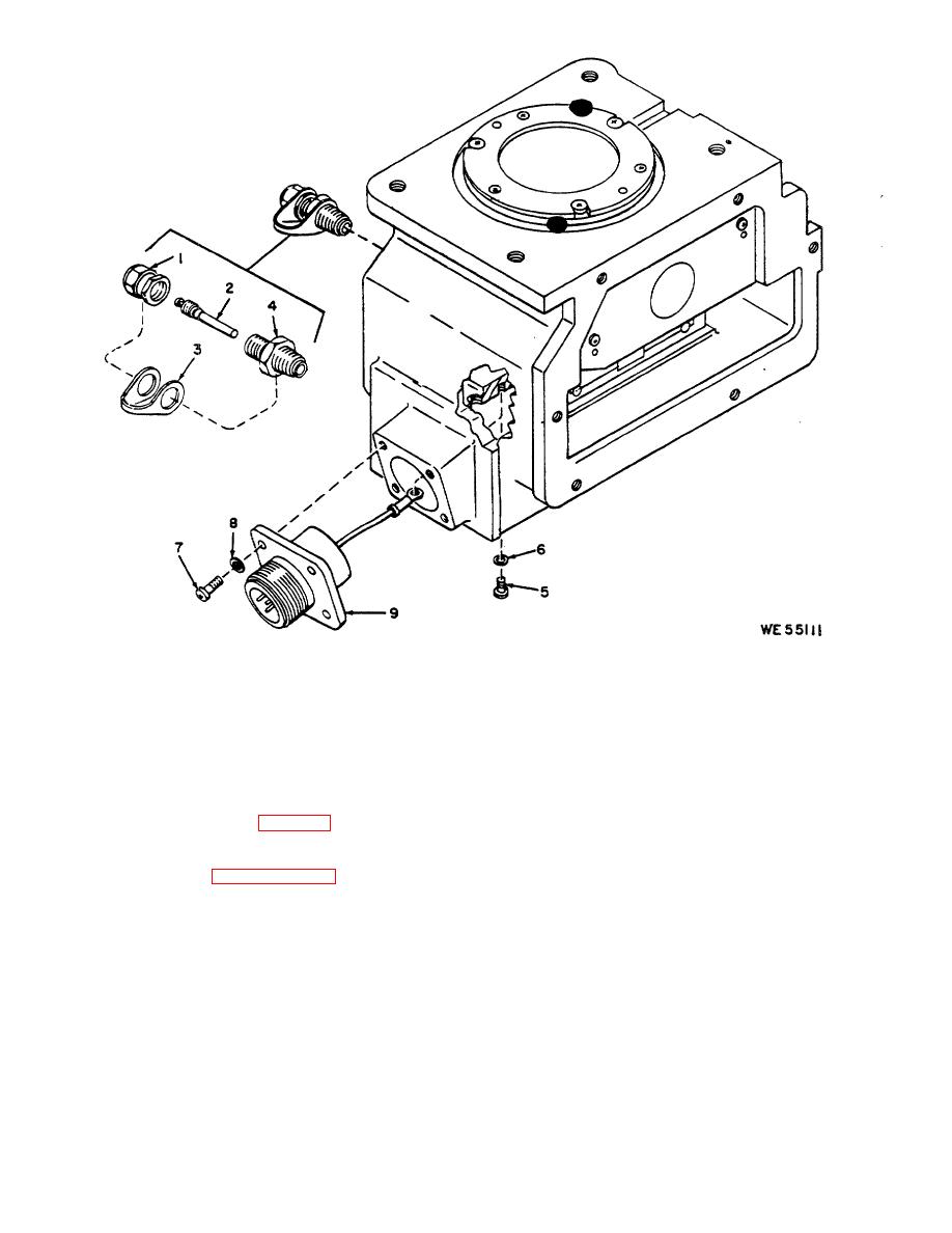 1 - -- Cap, valve, 8200055
5 - Screw, 4-40 x 3/16, MS35212-11
8 - Washer. lock. No. 4 (4),
2 - Air check valve. MS51377-2
6 - Washer, lock, No. 4, MS35333-87
MS35333-70
3 - Strap, 10516567
7 - Screw, 4-40 x 5/16 (4),
9 - Receptacle assembly, 8624721
4 - Valve stem, MS51607-1
MS651957-14
Figure 3-11. Reticle projector charging valve and receptacle assembly--partial exploded view.
(2) Inspect spring, check for compression.
3-16.
Replacement of Filter Assembly Positioning
(3) Inspect plunger assembly, check bearing
Plunger and Spring (Fig. 3-12)
for free rotation, rust or corrosion.
a. Disassembly.
c. Cleaning. Clean all parts with a cloth moistened
(1) Refer to paragraph 3-15 to remove and
with dry cleaning solvent.
replace the objective tube assembly.
(2) Remove item 5.
d. Repair. Repair is limited to replacement of the
(3) Use adjustable spanner wrench to remove
screws and spring.
item 6.
(4) Remove spring (7) and plunger (8).
e. Assembly.
(1) Apply a thin film of grease, MIL-G-23827,
b. Inspection.
to the bearing of plunger assembly (8). Insert spring (7)
(1) Inspect screws
for
broken
or
worn
into hole of the plunger assembly and install items into
threads, rust or corrosion.
housing.
3-14
|
|
Privacy Statement - Press Release - Copyright Information. - Contact Us |
