 |
|||
|
|
|||
|
Page Title:
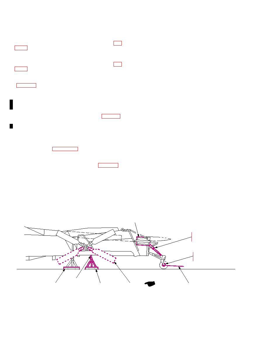
Figure 231. Positioning of Jack Adapters at Vertical Stabilizer |
|
||
| ||||||||||
|
|
 TM 55-1520-238-S
228.15 Load
Two
Horizontal
Stabilators.
e. Position Jack Adapter. Place jack
Position two stabilators on right side of cargo deck, un-
adapter under vertical stabilizer and align
der helicopter number two tail rotor and left engine (fig.
9 fittings (pin retainer) with vertical stabi-
FO2).
lizer upper sling pin receptacle and install
pins into receptacles.
228.16 Load Two Doghouse Fairings. Position
two doghouse fairings on cargo deck inboard of horizon-
f. Raise or Lower Adapter. Using jack
tal stabilators, under helicopter number 2 tailboom (fig.
handle raise or lower adapter and position
FO2).
pin retainers around 11 pins. Close pin
228.17 Load Two M230 Guns. Position two packed
retainers and rotate knobs to lock pins in
gun containers under helicopter number two fuselage
place.
(fig. FO2).
g. Center Jack Adapter. Center jack adapt-
228.18 Install Helicopter Number One and
er to vertical stabilizer by adjusting nuts on
Number Two Fuselage Station 450 Supports.
11 pins. Close pin retainers and rotate
Remove quick release pin holding FS450 jack pad wire
knobs to lock pins in place.
deflector. Secure wire deflector in open position. Jack
each helicopter at the tail landing gear jacking pad and
h. Rotate Jack Screw. With jack stand
aline a fuselage station 450 support (item 61, table 22)
adapter secured to vertical stabilizer, rotate
under each fuselage station 450 (tail boom) jack pad.
jack screw to raise vertical stabilizer and
Lower and remove jack.
relieve pressure on folding fixture support
228.19 Install Vertical Stabilizer Adapter Jacks on
rod pins. Adjust jack as required to remove
pins.
Helicopters.
a. Position Jack Adapter at Vertical Stabi-
i. Remove Support Rods. Remove both
support rods and reinstall pins into folding
b. Open 9 Fitting Assemblies. Using
fixture.
knurled knob, open 9 fitting assemblies
j. Wrap Support Rods. Wrap support rods
and remove 11 pin assembly (fig. 232).
with cushioning material (D5) sealed with
c. Loosen Nuts. Loosen, but do not re-
tape (D13). Stow rods for shipment.
move; two nuts on dash 11 pin assembly.
k. Secure Jack Adapter. Using tie downs,
d. Remove Jack Handle. Remove jack
secure jack adapter for transport. Stow jack
handle from retainer clips on jack stand as-
handle in retainer clips.
sembly.
VERTICAL STABILIZER
SUPPORT FIXTURE
LOCK-TAIL GEAR STR
LOAD / UNLOAD ONLY
ATTACH POINT FOR AFT
DIRECTION WINCHING
TIE-DOWN
FITTING
TWO TAIL ROTOR
VERTICAL
SUPPORT AFT
EXTEND POSITION
BLADES REMOVED
STABILIZER
FUS STA 450
(LOCKED)
M05-064A
Change 1
|
|
Privacy Statement - Press Release - Copyright Information. - Contact Us |
