 |
|||
|
|
|||
|
Page Title:
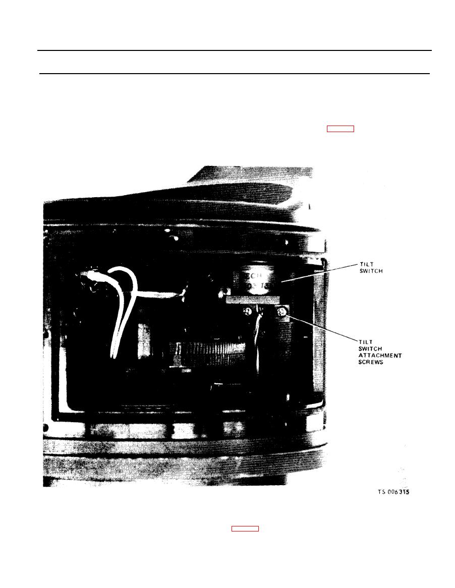
Figure 2-87. Tilt switch removal. |
|
||
| ||||||||||
|
|
 TM 5-6675-250-34
Table 2-1. Troubleshooting - Continued
MALFUNCTION
TEST OR INSPECTION
CORRECTIVE ACTION
the access.
(4). Disconnect the gearbox assembly electrical cable by rotating the connector mounting screws in
the counter clockwise direction. Alternate between the two screws every (2 to 3) turns. The
connector will be damaged if this technique is not followed.
(5). Tag and unsolder the electrical leads from the tilt switch terminals.
(6). Remove the two tilt switch attaching screws and remove the tile switch (fig. 2-87).
(7). Install the gearbox assembly in the housing and secure with two mounting screws. Connect and
solder the electrical leads.
(8). Install the anti-backlash setting tool (fig. 2-87) into the index hole of the upper gear half of the
follow-up gear set, with the handle of the tool towards the main connector cover.
(9). Place the thumb on one end of the gear set and the index finger on the other and slide the two
gear halves together so the ends are flush.
2-79
|
|
Privacy Statement - Press Release - Copyright Information. - Contact Us |
