 |
|||
|
|
|||
|
Page Title:
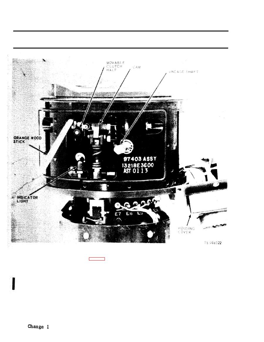
Figure 2-83. Gyroscopic reference unit uncaged indicator, |
|
||
| ||||||||||
|
|
 TM 5-6675-250-34
Table 2-1. Troubleshooting - Continued
MALFUNCTION
TEST OR INSPECTION
CORRECTIVE ACTION
c. Visually inepect lamp for a burned filament.
Replace a defective lamp.
(1). Unsolder and disconnect the lamp lead wires from terminal points E17 and E18.
(2). Remove the indicator mounting nut and remove the indicator light from the bracket.
(3). Apply MIL-S-22473, Grade N, Form R primer to the attaching parts threads and allow to air dry.
Apply locking sealant MIL-S-46163, Grade N, Type II, to the first few threads of the attaching parts.
s.
(4). Install a new indicator light and secure to bracket with the mounting nut.
(5) . Connect and solder the lamp lead wires to terminals E17 and E18.
(6). Install housing cover and secure with attaching screws.
(7). Place UNCAGED knob onto the switch shaft, allowing sufficient space between the knob end
GRU housing to prevent binding. Tighten knob setscrews.
Step 5. Check for improper adjustment of caging solenoid.
If the caging solenoid does not operate properly, check for improper adjustment.
Adjust caging solenoid as follows:
|
|
Privacy Statement - Press Release - Copyright Information. - Contact Us |
